• Welcome to The Truck Stop! We see you haven't REGISTERED yet.

    Your truck knowledge is missing!
    • Registration is FREE , all we need is your birthday and email. (We don't share ANY data with ANYONE)
    • We have tons of knowledge here for your diesel truck!
    • Post your own topics and reply to existing threads to help others out!
    • NO ADS! The site is fully functional and ad free!
    CLICK HERE TO REGISTER!

    Problems registering? Click here to contact us!

    Already registered, but need a PASSWORD RESET? CLICK HERE TO RESET YOUR PASSWORD!

Working on a "next-level" fuel system

Yeah, if you are going to have the fuel in constant circulation because you want to polish (super filter) the fuel, Then a lot of circulating fuel makes sense. It doesn't add up to me.

I learned fuel systems on older carbureted gassers, so my default is still "just keep the bowl full". My line of thinking is, If you add up how much fuel has to get pumped to the ip and keep it up to the design pressure, everything else is just a waste. Is there a specific pressure we want to keep the return fuel line at?

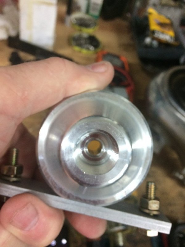
With the pic of Warwagon's recent flap in ip feed line, I am rethinking how connections should be done to the ip and fuel pressure gauge. He mentioned pressure gauge reading the ip housing...
 
That was the impression I got from @WarWagon.

My thought was a "T" fitting that screws into the pump housing. one side of T goes to pressure sender/ gauge. The other connection (the more in line one) going to a stainless steel tube that is fed from the filter. No flexable hose. Secure it like the injector lines are- just supported from vibration issues. eliminate hose failure at that point.
Gotcha. I like the idea except that it may make the IP unusable as a future core. I do like the T idea and I think I'll do that. Your hard line idea only works for people still using the factory FFM.
 
The T just threads in like the barbed fitting. Would be replaceable.

Having the metal T where the gauge attaches is the key, more so than the hard metal line from filter to ip. Imagine that inside hose flap like WarWagon’s (which has happened to others too). Even if it is at the T, the pressure would be cut to the ip AND the gauge. He had a gauge on the drain line like GM says to do and read good pressure. But because the gauge wasn’t reading immediately at the ip inlet, it was eliminated as culprit.

Leroy’s awesome ffm filter tap for gauge is a great idea, but because I have experienced the same issue, I tell people Leroys is an ok alternative, hut best is at the ip.

When I did my T using hose, the metal fittings could touch. The hose sealed the outside, but didn’t span any distance between them just for this issue.
 
Yeah, if you are going to have the fuel in constant circulation because you want to polish (super filter) the fuel, Then a lot of circulating fuel makes sense. It doesn't add up to me.
Is there a specific pressure we want to keep the return fuel line at?.
The pumps builder should be able to address that question in detail.
 
Yeah, if you are going to have the fuel in constant circulation because you want to polish (super filter) the fuel, Then a lot of circulating fuel makes sense. It doesn't add up to me. ...

IMO Its more a matter of having shorter line runs and specifically line diameter that can be tinkered with at much less cost.
Diameter matters and that requires doing the math to get into the ball park of properly sized feed diameter and even playing with feed & return sizes.

It does not end there because type of line and fittings must be up to the task of allowing maximum flow 'always' lowest friction, and even anti-static, its become so high tech now that AN fuel fittings can be had w/internal Teflon coating.

Then the injector return ports become a restriction as fuel delivery is increased beyond design parameters so it gets more technical as ones quest for more fuel is applied.

I include the following link 'again' on the importance of line diameter however it does not end there because in all systems clean unrestricted flow then becomes the issue.

http://www.torkteknology.com/technical-article-2-the-diesel-fuel-system-inlet-line/
 
Last edited:
A sump scares me on the street too. Curbs (sometimes those get hopped ;)) or branches in the road could be a concern for me. I'd like to keep everything for the fuel system above the frame rails and fuel tank skid plate.

I always like to keep things out of harms way. I've had and seen things that you would never think would or could happen. Front brake flex line ripped off by soybean stubble. Frozen soybean stubble stuck through a tire, ruining the tire.

A barbed wire fence buried in grass.
 
I figured I'd dissect the Fass FPR-1001 FPR since I have never seen the inside workings of a fuel pressure regulator. So it appears that all three ports are one common area so I guess the 1/8 " NPT port for the gauge would measure the housing pressure of the FPR, which I guess is the pressure going to the IP no matter which way you plumb it. It appears that the diaphragm is just spring loaded pressure against the pressure of the lift pump. Tighten the set screw appley's more spring pressure. It looks like if you tighten enough it would block off the return port. It also appears that when boost pressure is introduced into the upper housing on the topside of the diaphragm it would apply pressure to the aluminum piece that appears to shut off flow to the return line therefore raising pressure I guess. What happens to the volume when the spring pressure is increased? Restriction? I've attached the instructions link along with some photo's. I would like to do this to a Fuelab 515 series regulator, they have more specific pressure ranges if you look at the technical data sheet (link below).

https://fassride.com/wp-content/uploads/2017/12/Fuel-Pressure-Regulator.pdf

http://fuelab.com//wp-content/uploads/2012/10/105020100-Regulator.pdf
 

Attachments

  • 001.JPG
    001.JPG
    84.5 KB · Views: 4
  • 002.JPG
    002.JPG
    89 KB · Views: 4
  • 003.JPG
    003.JPG
    64.9 KB · Views: 5
  • 004.JPG
    004.JPG
    110.9 KB · Views: 6
  • 005.JPG
    005.JPG
    87.4 KB · Views: 6
  • 006.JPG
    006.JPG
    102 KB · Views: 6
  • lh port.JPG
    lh port.JPG
    86.7 KB · Views: 6
  • rh port with pres port.JPG
    rh port with pres port.JPG
    87.1 KB · Views: 5
  • return port.JPG
    return port.JPG
    82.3 KB · Views: 5
I figured I'd dissect the Fass FPR-1001 FPR since I have never seen the inside workings of a fuel pressure regulator. So it appears that all three ports are one common area so I guess the 1/8 " NPT port for the gauge would measure the housing pressure of the FPR, which I guess is the pressure going to the IP no matter which way you plumb it. It appears that the diaphragm is just spring loaded pressure against the pressure of the lift pump. Tighten the set screw appley's more spring pressure. It looks like if you tighten enough it would block off the return port. It also appears that when boost pressure is introduced into the upper housing on the topside of the diaphragm it would apply pressure to the aluminum piece that appears to shut off flow to the return line therefore raising pressure I guess. What happens to the volume when the spring pressure is increased? Restriction? I've attached the instructions link along with some photo's. I would like to do this to a Fuelab 515 series regulator, they have more specific pressure ranges if you look at the technical data sheet (link below).

https://fassride.com/wp-content/uploads/2017/12/Fuel-Pressure-Regulator.pdf

http://fuelab.com//wp-content/uploads/2012/10/105020100-Regulator.pdf
Nice! Yeah that surprised me how wide the range was for the FASS regulator having already looked at the Fuelab regulators and noting the different pressure ranges for theirs. If I go that route (which I am leaning towards) I will share the same info if possible.
 
Just order it from Thoroughbred Diesel and then return it. LOL! I didn't plan to do this nor do I practice it but after numerous talks and miss information with the the so called "TECHS" at Fass that's what has happened in this instance. The only thing I don't like about the Fuelab unit is the pressure range is either 10-25psi or 25-90psi. Nothing in between, I think you are probably close to the upper end pressure range so I would like to find one that had a range of like 10-30 or 20-40psi or something along those lines. Seen anything like this?
 
Last edited:
Just order it from Thoroughbred Diesel and then return it. LOL! I didn't plan to do this nor do I practice it but after numerous talks and miss information with the the so called "TECHS" at Fass that's what has happened in this instance. The only thing I don't like about the Fuelab unit is the pressure range is either 10-25psi or 25-90psi. Nothing in between, I think you are probably close to the upper end pressure range so I would like to find one that had a range of like 10-30 or 20-40psi or something along those lines. Seen anything like this?
Yes I saw those same numbers. I was thinking I would contact them and either see what they recommend or see if they can put one together with a custom calibration.
 
Good find! Well there's one instance where the use of a true return-style fuel system made the fuel delivery to the IP more consistent.
Notice on post # 13 of that thread 'he never connected to the boost reference port' so there would more benefits to his setup if connected.
 
Hey guys, I've been brain storming again LOL. So if the FPR acts like when you kink a garden hose slightly it restricts flow (volume) but increases pressure, are we losing needed volume in our quest for pressure? Maybe I'm overthinking this.
 
Hey guys, I've been brain storming again LOL. So if the FPR acts like when you kink a garden hose slightly it restricts flow (volume) but increases pressure, are we losing needed volume in our quest for pressure? Maybe I'm overthinking this.
This is where the flow rate of the pump comes into play. Flow (volume, ie. gallons/hour) is the main criteria for pump selection. The ability of that pump to flow at various pressures is the other criteria. So yes, you select a pump that is able to make the volume of fuel needed at the desired pressure. It's disappointing that it's so hard to find a pressure v. flow graph for most pumps. That is one nice thing about the Walbro pumps - they have that graph right on their website. Here is the graph for the GSL392, which is the highest output pump in this series. GSL392 graph.jpg

Now here is the graph for the GSL395, which is the smallest in this series. It makes less volume and also can't maintain that volume under much of a pressure demand.

GSL395 graph.png

As long as the pump is properly sized for the application, the regulator won't be a problem.
 
Back
Top