• Welcome to The Truck Stop! We see you haven't REGISTERED yet.

    Your truck knowledge is missing!
    • Registration is FREE , all we need is your birthday and email. (We don't share ANY data with ANYONE)
    • We have tons of knowledge here for your diesel truck!
    • Post your own topics and reply to existing threads to help others out!
    • NO ADS! The site is fully functional and ad free!
    CLICK HERE TO REGISTER!

    Problems registering? Click here to contact us!

    Already registered, but need a PASSWORD RESET? CLICK HERE TO RESET YOUR PASSWORD!

Working on a "next-level" fuel system

IMO if it matters, moving the fuel supply from your main tank to a small surge say one (1) gallon tank is about the cheapest route because of the shorter line runs and easy adjusting of the line diameter.

Consider, at the track how much fuel do you actually use on a run? How about when passing another vehicle on the road? If perhaps you are worried about hills and mountains then a slightly larger tank is in order or go big and do the entire system using your existing tank.

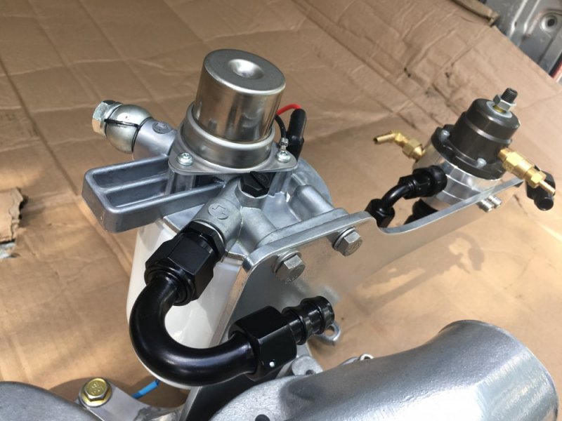
I'll be building my surge tank up close to the engine bay for the Cummins w/it's P7100 IP which requires 5/8" ID feed to provide proper fueling at speed @ WOT. I'm also staying with the mechanical pump because FERM and other experts pointed out it's plenty for my build.

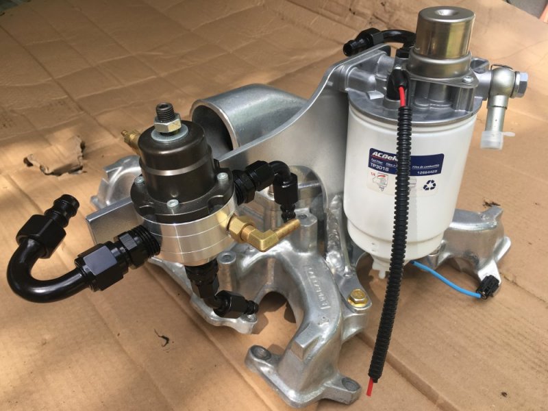
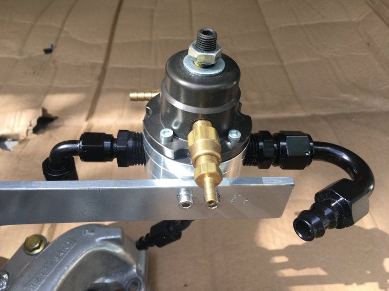
Many individuals are intimidated by AN fittings and lines however; once you get the hang of assembling your own you'll want to use them always.
 
Did I already say this? If so, sorry.

I understand the pump builders built your db2 with that 5/16 to -6 fitting in it. But they grew their reputation on building these for Fords which have a larger inlet fitting factory.

At it’s core, a bigger opening allows faster and smoother refueling. If you keep the pressure the same but increase the area then volume flow increases. When it flows faster there is less turbulence then volume and pressure is more constant.

This is something that has confused me from go. My hopped up ip(s) had 1/2” hose feeding tank to ip, with custom made funnel tapered down to an id of 3/8.

Later he (pump builder) enlarged the return to 5/16 to increase flow and maintain pressure.

Will, we are dealing with mostly unknowns when it comes to fueling a diesel VS gasoline IMO perhaps the best information on just how bad the BIG 3 have defiled diesel product lines.
The following links I may have posted before but well worth a reread.

https://www.torkteknology.com/technical-article-1-cummins-lift-pump/
https://www.torkteknology.com/technical-article-2-the-diesel-fuel-system-inlet-line/
 
Well I know how everyone loves diesel porn so here are some photo's of one of the fuel system's I've been working on. As stated earlier in this thread there is no DATA to show that there is any advantage to using this system. This system also requires dropping the fuel tank and adding a 1/2 inch pickup tube so I'm not sure if and when I will actually be putting this setup in service
 

Attachments

  • IMG_0145.JPG
    IMG_0145.JPG
    117.1 KB · Views: 28
  • IMG_0146.JPG
    IMG_0146.JPG
    119.9 KB · Views: 29
  • IMG_0147.JPG
    IMG_0147.JPG
    119.4 KB · Views: 28
  • IMG_0148.JPG
    IMG_0148.JPG
    113 KB · Views: 24
  • IMG_0149.JPG
    IMG_0149.JPG
    109.5 KB · Views: 23
  • IMG_0150.JPG
    IMG_0150.JPG
    85.4 KB · Views: 23
  • IMG_0151.JPG
    IMG_0151.JPG
    104 KB · Views: 21
I've been doing some power reading over the last few days as I dive back into my project. This is one of the threads I have went through and I will add a little to it.

I have a background in the world of mild street cars. Some that I built for myself and some I have built for others. As far as pumps and regulators go I can tell you my experience in the gasoline/e85 world.

Much of this you may have figured out already.

Lets say you are using a pump capable of 60gph at 55 psi, no internal bypass.

When using a regulator your pressure will be rock steady at what ever device you are feeding up until you feed past the ability of the pump. If you set that regulator to 25psi, the pressure will not move unless you are using more fuel flow than the pump is capable of. Of course this is considering the lines running to the pump and returning to the tank form the regulator are the appropriate size.

The vacuum/pressure reference port is changing the fuel pressure according to manifold conditions. In a gasoline engine for example. The vacuum/pressure line from the regulator to the intake manifold is removed and the regulator is set to 39 psi (just an example) while the pump and engine is running. Then the vacuum/pressure line is re attached to the regulator. If the engine (gas in this situation) is pulling vacuum it will drop the pressure according to how much vacuum there is. The reason for this is because the pump/regulator is feeding directly to the injectors and a pulse from the ECU opens the injector for a varied amount of time according to load demand (idle-WOT). If there is vacuum present in manifold, there is no need for the higher fuel pressure to overcome atmospheric pressure when the injector opens. You could say that the fuel is sucked from the injector. When the throttle opens and the vacuum drops to 0 (or close to 0), then you have the 39 PSI of fuel pressure. Now lets say you have a boosted application (turbo or supercharger). The manifold pressure goes to 10 psi (example) the regulator gets 10 psi applied to the back of the diaphragm and if its a 1:1 regulator it will add 10 psi to the fuel pressure to overcome the 10 psi of manifold pressure pushing back on the fuel when the injector opens.

Relating to the 6.5

I would not use the pressure/vacuum reference port for our application because we are feeding an injection pump and not the injectors directly. I know that there was discussion about feeding the modified DB2's 25psi, but I would not want to go up from there at a 1:1 ratio according to manifold pressure. It will hold steady at 25psi with the regulator no matter what your fuel demand is. Considering you have a pump and fuel lines the correct size.

This may already be known, but I didn't see anything discussing the purpose of the vacuum/pressure reference port on the regulator.
 
Well I know how everyone loves diesel porn so here are some photo's of one of the fuel system's I've been working on. As stated earlier in this thread there is no DATA to show that there is any advantage to using this system. This system also requires dropping the fuel tank and adding a 1/2 inch pickup tube so I'm not sure if and when I will actually be putting this setup in service


Nice Piece!

If I decide to go with one of the modified DBS's my fuel system setup will be like this. It probably wont be as pretty, but it will function the same.
 
I've skimmed through this thread. And in my opinion I see no reason to run a boost referenced fuel pressure regulator on a 6.5. You can give it all the pressure you want your not going to increase the pressure and volume output of the transfer pump inside the pump. A simple FASS system with 10psi and enough volume to keep up with the injection pump is all you need. Keep it simple I say.

The FASS system for the duramax only runs about 10-12psi and it can keep up with 700hp plus trucks. Volume is the important part.

Only way I could see using a boosted referenced fuel pressure regulator would be of you removed the transfer pump and forced feed the pump with over 150psi of fuel. But that will take alot of modifications to the pump and would only be good for racing/pulling.
 
Hey I just thought I would bring this thread back to life since I'm dead in the water with the Burb for now. So can anyone tell me why Wes @ CDD is using an adjustable boost, boost referenced fuel pressure regulator on his DB2 pumps? I would ask him directly but I have been unable to contact him. From the looks of Nates fuel system on his 94 K3500 it looks like he could make it the same with just the addition of a boost hose and a adjustable boost knob. Correct me if I'm wrong Nate.
 

Attachments

  • CDD FPR.jpg
    CDD FPR.jpg
    191.1 KB · Views: 4
  • CDD adjuster.jpg
    CDD adjuster.jpg
    206.8 KB · Views: 4
Last edited:
He is using it to adjust inlet pressure. More inlet pressure= more cc output. Its helps with higher rpm fueling on these style rotary pumps. You can only do this if the timing is locked. Otherwise it will advance the timin when you increase pressure.

If your timing advance is still functional. Then you could use a 1:1 boost referance fuel pressure regulator to increase pressure only under boost. So you could keep stock 10psi if inlet pressure (25psi on yours) at idle to keep the timing from advancing. Then have 30psi (45psi on yours) at 20psi of boost. That will increase fueling. The key is keeping you inlet pressure lower than transfer pump pressure to avoid messing with the timing
 
I guess I'm confused on the workings between the transfer pump timing and the advance servo timing, I see how the advance servo moves the cam ring when the throttle is opened but not sure on the transfer pump. So is transfer pump timing controlled by RPMs or fuel pressure? Sorry for the 100 questions but one never learns if he doesn't ask. LOL
 
Transfer pump pressure is controlled by rpm. Kinda like govenor pressure on an old automatic transmission. The pump uses Transfer pump pressure to move the advance piston though passages in the piston controlled by the servo. If you increase inlet pressure higher than Transfer pump pressure it raise Transfer pump pressure to the same psi and that will mess with timing at idle
 
Hey I just thought I would bring this thread back to life since I'm dead in the water with the Burb for now. So can anyone tell me why Wes @ CDD is using an adjustable boost, boost referenced fuel pressure regulator on his DB2 pumps? I would ask him directly but I have been unable to contact him. From the looks of Nates fuel system on his 94 K3500 it looks like he could make it the same with just the addition of a boost hose and a adjustable boost knob. Correct me if I'm wrong Nate.

Rockabilly answered that question better than I could have so I think you’re set there.

I haven’t used the setup that CDD is using, but in theory I much prefer how I was controlling the low end fueling of my injection pump on the Tahoe using an aneroid and an electronic boost controller. It was very flexible and works with a pump that still has dynamic timing. I will be putting that setup in the 94 this summer. This fall I intend to expand on that in my other truck, Krovvy. I am going to use an aneroid on that truck, but use a more sophisticated boost controller that can have multiple set points based on rpm and/or other parameters. It should work pretty slick, but time will tell. It will be like AFC Live for a DB2, but honestly I’d dare say even better than AFC Live, but again, time will tell.

We may play with the boost-referencing feature in the fuel regulator, but not so much to limit low end fueling, instead to augment top end fueling. I think that would need some additional controls though so it doesn’t add the extra pressure before you want it to.
 
Nate do you have any postings showing your Tahoe setup? I thought I had read most of your threads but maybe I missed something somewhere.
 
Thanks Nate, that's cool stuff. I'm sure you've thought about this but I was trying to figure out how to adjust the Puff Limiter housing with a cable and knob sorta like the P pump Attitude Performance adjuster but I can't figure out how with the GM intake manifold so close to it. That with the adjustability of the boost source would be pretty cool. Maybe you have come up with something already?
 
Thanks Nate, that's cool stuff. I'm sure you've thought about this but I was trying to figure out how to adjust the Puff Limiter housing with a cable and knob sorta like the P pump Attitude Performance adjuster but I can't figure out how with the GM intake manifold so close to it. That with the adjustability of the boost source would be pretty cool. Maybe you have come up with something already?

I see, so you are thinking you'd want to not only limit when the boost is allowed to push on the diaphragm, but also independently control how far it can travel. I hadn't thought about that. Off the top of my head, it could be done with a second boost controller so you'd have one to cut in and one to cut out, but that isn't a very elegant solution. I know some boost controllers have an over-boost feature, so that maybe could be put to use - once it reaches a certain pressure threshold perhaps another valve could be opened to maintain an upper limit.

I guess as I'm thinking about it though, I have to wonder why we would want to do that. The aneroid and boost controller are there to cut over-fueling before the engine can burn it, so what are you trying to accomplish with a limiter? A valet mode? Something so you can mat the pedal and not have to worry about EGTs on a long hill? I can't recall if the aneroid can limit the metering valve and not the governor so you could carry higher rpms with less fueling. Maybe something to look into further.
 
Nate I should have added, I have not had the pleasure of running a pump with a puff limiter yet so maybe once you get the housing dialed in, the boost reference adjustability is enough. You would know better, I'm just always brain storming one way or the other, LOL.
 
Back
Top