• Welcome to The Truck Stop! We see you haven't REGISTERED yet.

    Your truck knowledge is missing!
    • Registration is FREE , all we need is your birthday and email. (We don't share ANY data with ANYONE)
    • We have tons of knowledge here for your diesel truck!
    • Post your own topics and reply to existing threads to help others out!
    • NO ADS! The site is fully functional and ad free!
    CLICK HERE TO REGISTER!

    Problems registering? Click here to contact us!

    Already registered, but need a PASSWORD RESET? CLICK HERE TO RESET YOUR PASSWORD!

Project Frankensquare

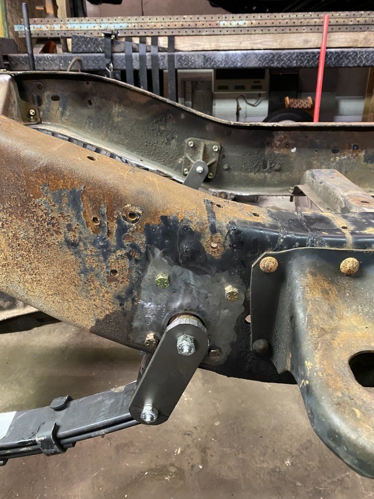
I got the rear spring mounts in the frame located. I found the proper location for the main hole then put the mounts in place and figured out where to locate the bolt holes. I got that mostly done Friday night.

Saturday I went out of state to buy a used horizontal bandsaw so I didn’t get any truck stuff done. Today I got lots done. I finished up that mount. After that, I drilled the holes for the top of the motor mount brackets and got bolts installed.

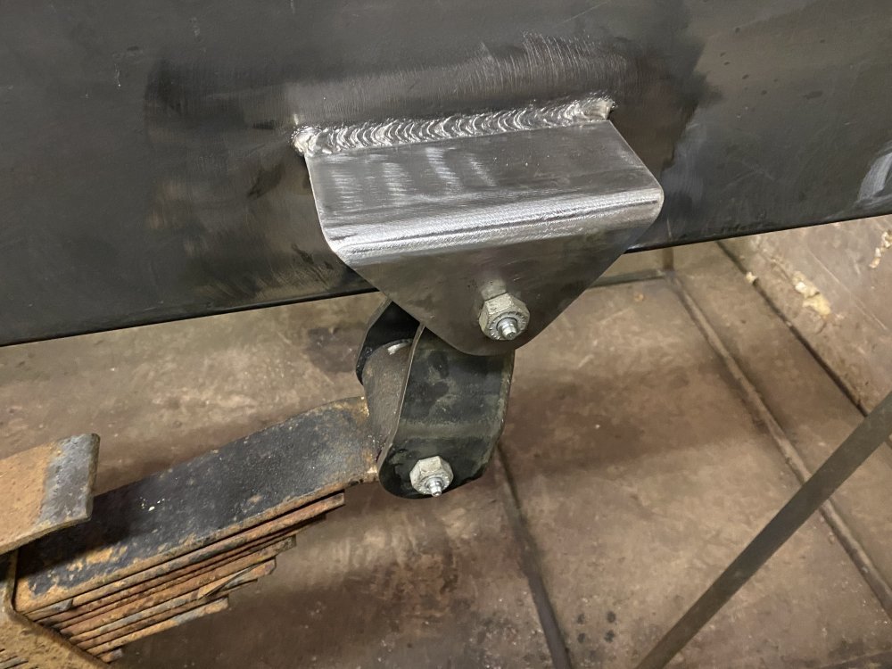
Next up I’m made the spring shackles out of some 3/8” x 2” steel. Once that was done then I could install the bushings I got from Offroad Design into the springs and upper mounts.

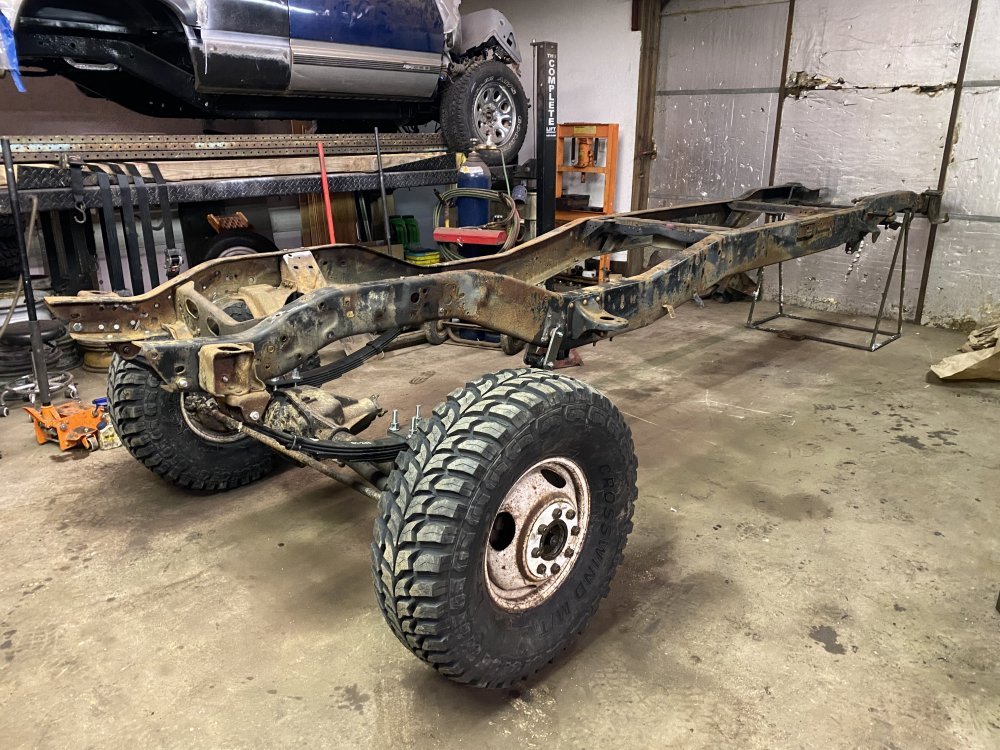
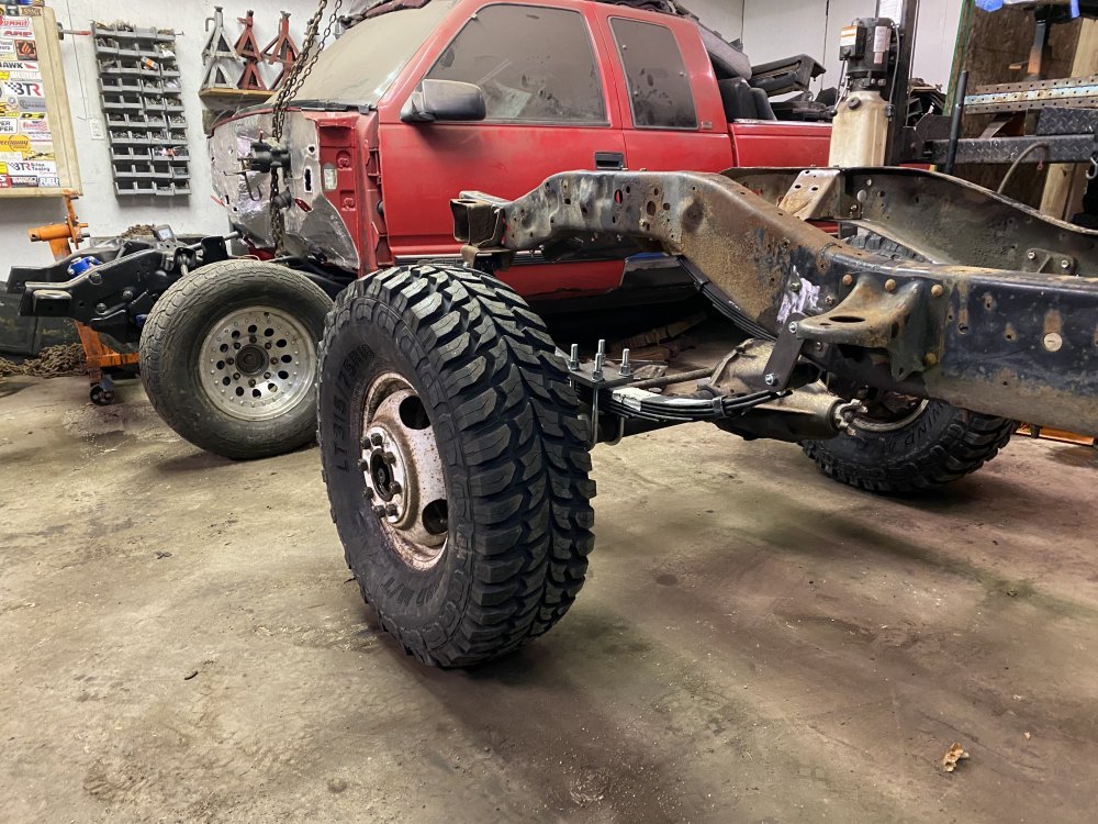
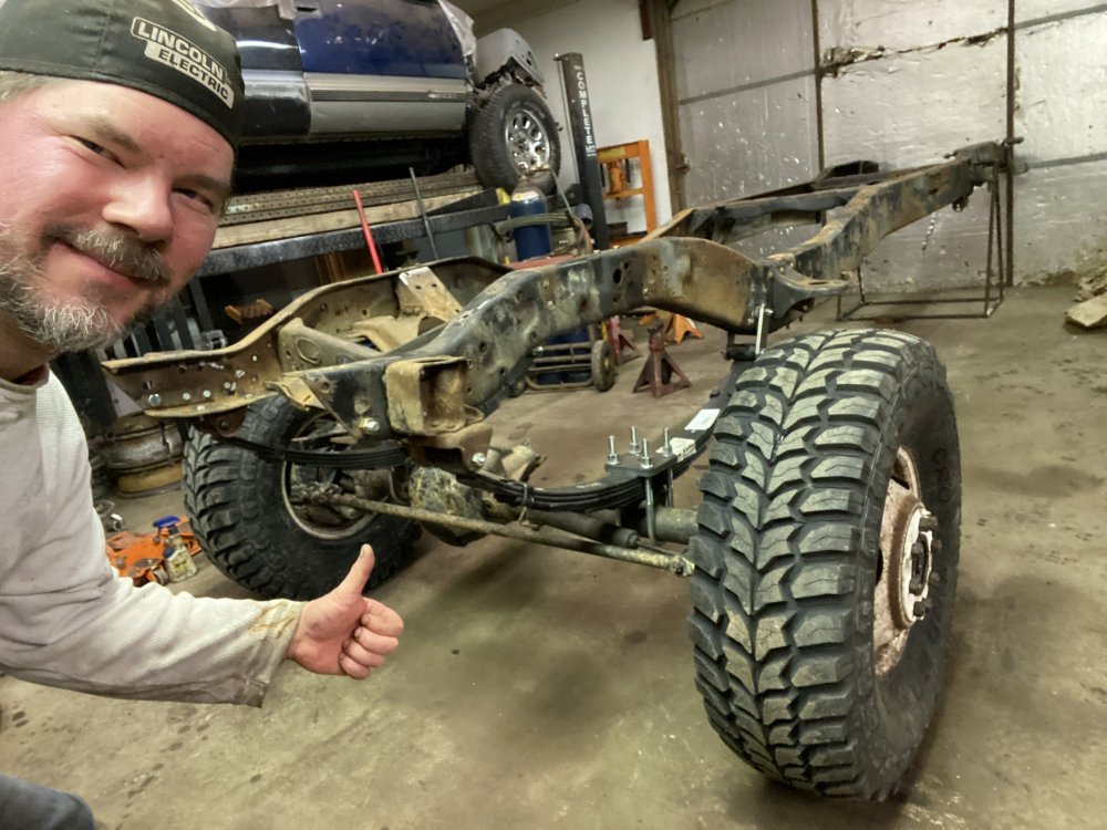
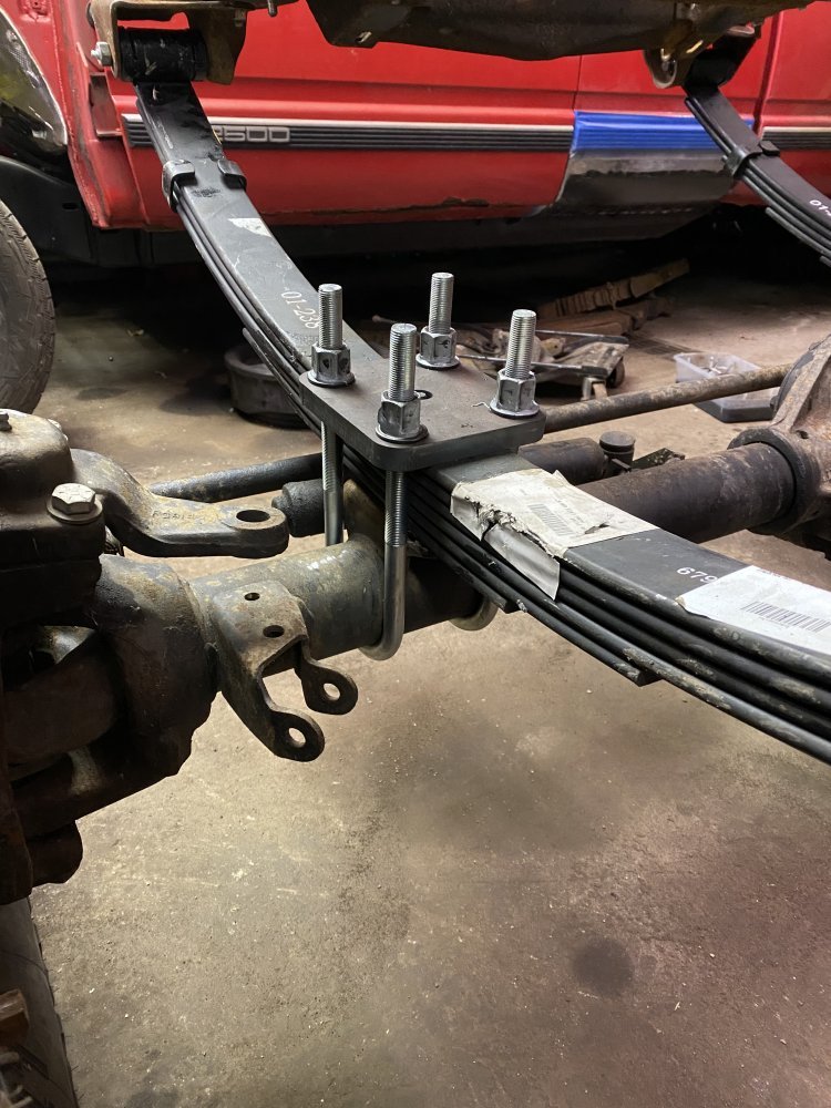
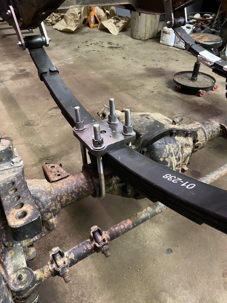
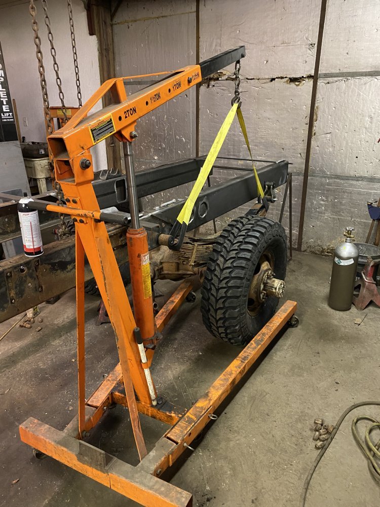
With the springs in place I could then work on the axle. I was going to clean and pack the bearings and stuff, but I know it will be coming back apart again for brake rotors so I just threw the dually hubs onto the axle as-is. I bolted it to the springs with the ORD u-bolts and plates and then I could finally do the thing I REALLY wanted to do…..put the wheels on the front.

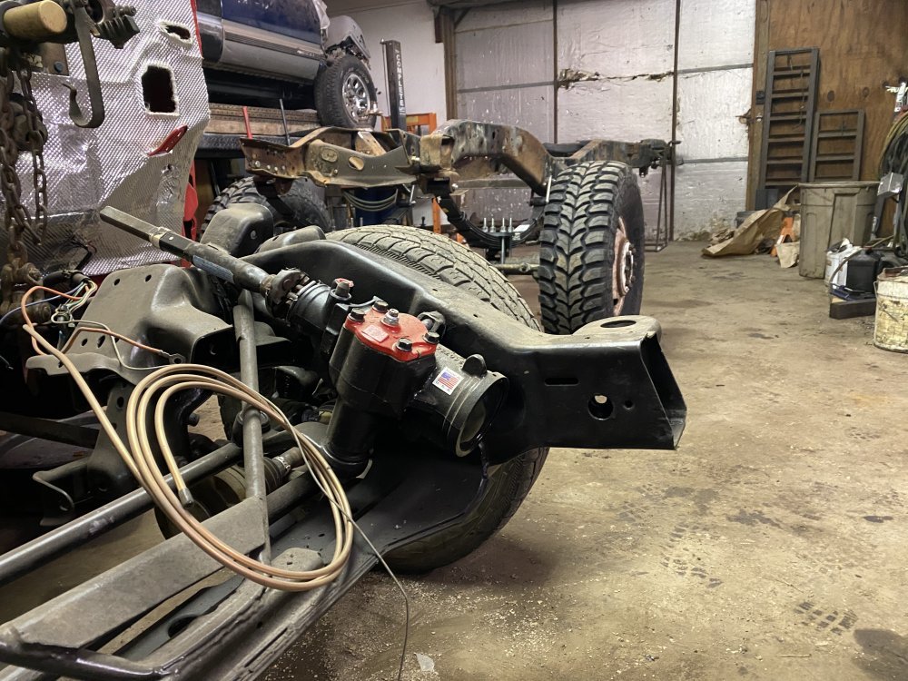
Man, this thing is gonna be tall. Should be cool. 😎 On to the rear frame rails now.

C5F3E53F-C5D1-4739-BD8E-D82499650E7D.jpeg778431EA-1694-40DB-BA8A-80465D775840.jpeg25B57633-D955-461F-9B65-48D385643270.jpeg06F99CA2-BD14-46AD-8B8E-BF4CEE727658.jpegAA2F5EAB-424D-4C1A-8E46-718F855AC778.jpeg2EB224D4-63F4-4C43-AEDD-3376FF01C1E9.jpegDFAF18F8-E1C9-4DD1-A563-C089D1AC06D8.jpeg
 
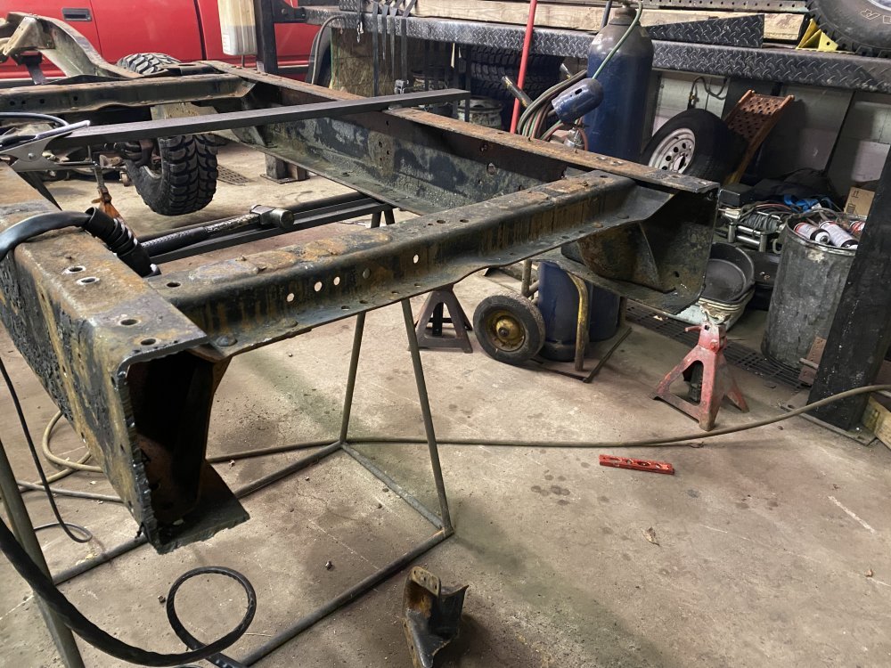
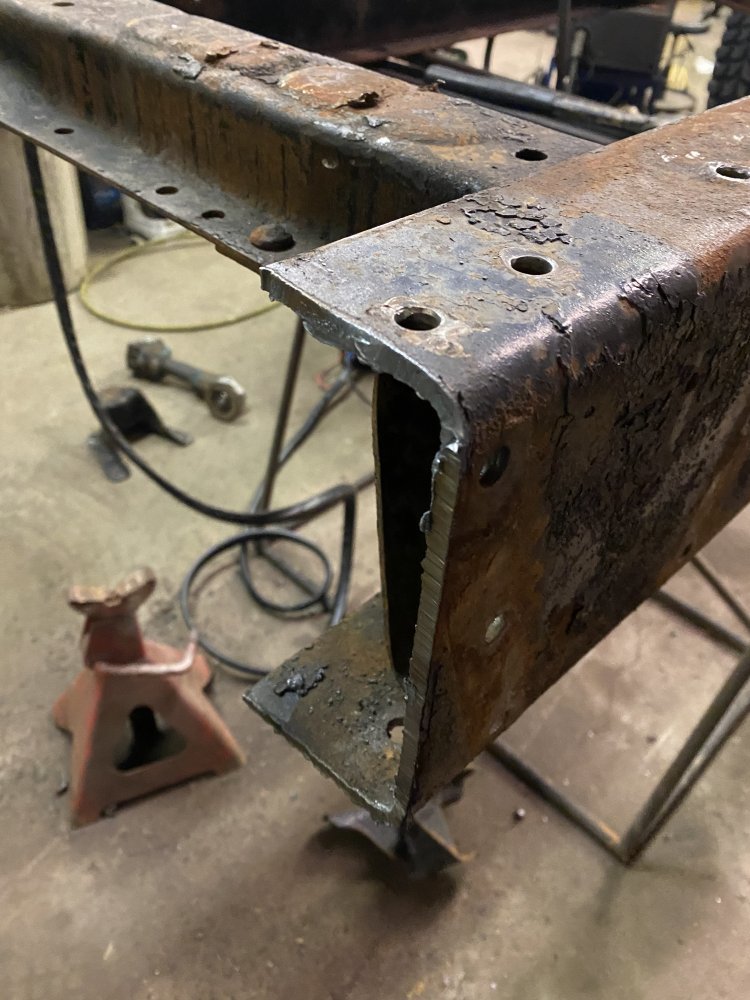
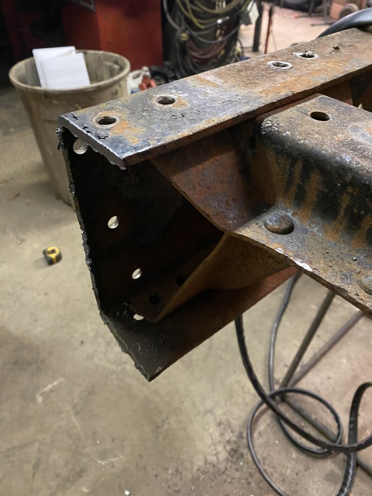
I’ve been playing with my new plasma cutter this week. Earlier this week I cut the rear of the rails off where they arched up over the axle from the factory. I left a short section where the bottom of the rail kicks up so I could slide some tubes over the old rails for a sleeve connection.

15A7258E-7591-4FBD-946C-A87F0B7E586A.jpegB12E358F-3E40-424F-8AC1-5418000182E0.jpeg2C623FA3-B00E-446C-9F1D-B21B26AEB32B.jpeg6DC8BE97-32EA-4164-A0CC-BD3624E041D1.jpeg6F57CA33-44F9-4829-A13A-6909E462FB16.jpeg

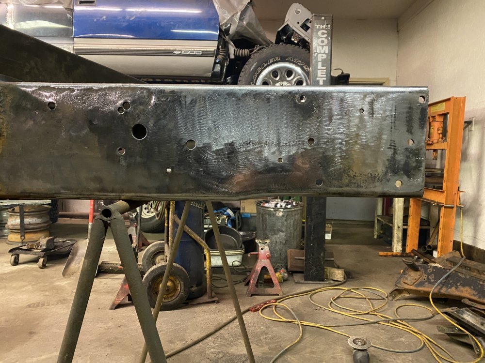
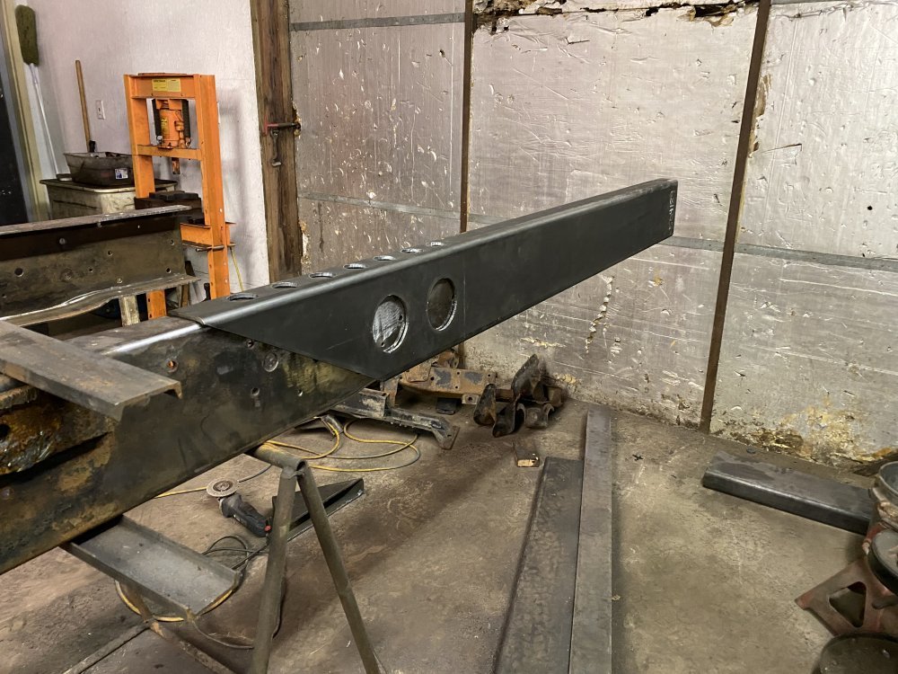
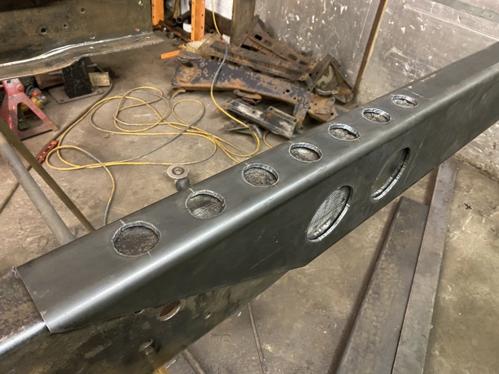
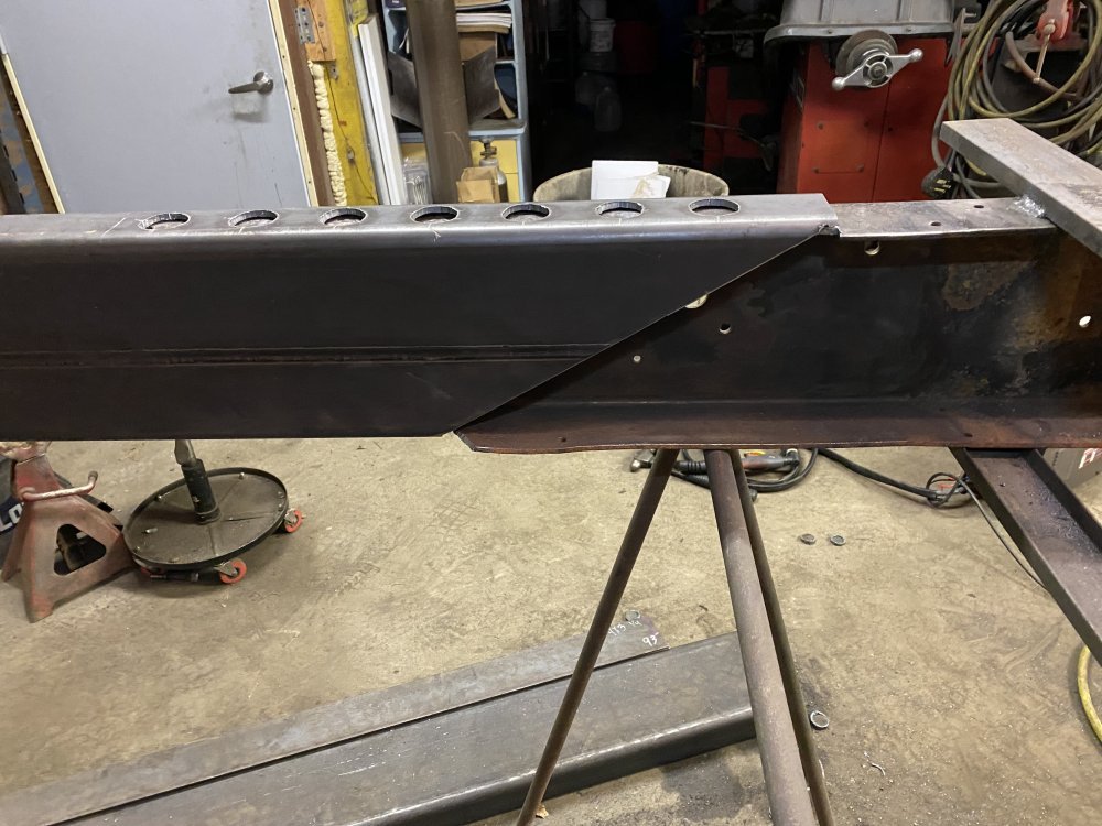
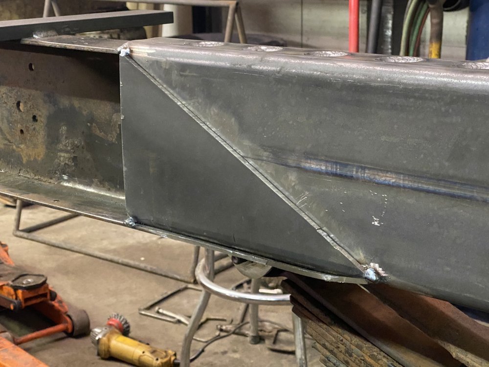
With the ends removed I could finalize my plan for the rails. Since I’m lifted, I no longer need the clearance for the axle. I also wanted to make the fabrication of the spring brackets simpler with the bottom of the rails being straight and to have the bottom of the rail a little lower so I didn’t have to make the brackets as long. I went to Alro yesterday and found 2 perfect pieces of rectangular tube: 3x8x1/4 wall that were just barely longer than I needed. Score! Last night I got one tube cut how I wanted, but ran out of time to do the deburring before dinner, so I had to do that this evening before I could slide it on.

E86327D1-3931-4ABD-83A4-0DDBA78E3F83.jpeg6C969620-E5BB-4A91-9195-BE93361086AA.jpegB862A588-E10A-4DE6-AA56-0237ADB54BD6.jpegFB9B2CF7-A9CA-4722-B9B2-9E325BA227FA.jpeg


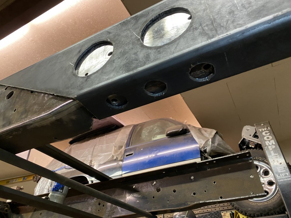
I think it’s a great start. I will not only be welding along the diagonal edge, but also inside each of those holes - should be plenty strong, plus I have some other overlapping plates in mind. Now to make the second rail.
 
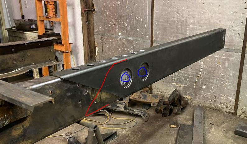
The fact that you angle cut the splice is wise. For what it's worth, due to the axle location (assuming it's behind your splice, if doing this again, I would have the angle this direction, though (indicated with red).
1675442056663.png
The plug welds top and bottom flanges are far more critical than those on the web.

Nice work. Do you have a shop you work with on the material or did you form those with your own brake press?
 
The fact that you angle cut the splice is wise. For what it's worth, due to the axle location (assuming it's behind your splice, if doing this again, I would have the angle this direction, though (indicated with red).
View attachment 79336
The plug welds top and bottom flanges are far more critical than those on the web.

Nice work. Do you have a shop you work with on the material or did you form those with your own brake press?
Thank you for the feedback. The axle will be straddling that joint, though I don't have the exact location of the hangers yet. I did the angle in that direction because at the leading edge of the bottom of that extension is where the original frame rail kicks up (you can just barely see it in that picture if you look closely), and the height of the rail at that kick up was a perfect slip-fit for the inside dimensions of the 3x8x1/4, so I was taking advantage of that feature, but still trying to add as much weld seam length as possible, so that's why I went in that direction. Thinking back to my Statics class......are you thinking that if the axle was completely behind that splice that it would be better for the load to be largely compressing the weld seam rather than having it in tension?
 
Top weld seam in compression is how I saw it, bottom in tension. Weld seam as you have it could have a "peeling away" effect if a failure was to happen, where the weld at the bottom sees the tensile load more than the rest. If the seam was in the other direction, the whole length of the weld sees the tensile load somewhat equally and all pulls together. I'm taking a lot of liberty with my assumption, however. Without seeing the big picture just yet, keep my suggestion at arm's length.

Axle straddling the joint helps to paint the picture.

Regardless, with the overlap you have and the flange seams being offset, I would estimate it will be a non-issue.
 
Yes, compression better than tension. That Minor in Physics and Major in Geology having practical applications in other situations - like when I had my construction business recognizing that when I was digging footings in loess soil I didn't need to use forms as the footing walls were self-supporting (one of the characteristics of loess, which is wind deposited "rock flour" from glacial grinding and is found in thick deposits as the hills on either side of the Missouri River in Nebraska and Iowa, as well as throughout Iowa, Illinois, Ohio, Michigan, Wisconsin, Indiana, Minnesota and the Midwest) and wouldn't collapse in. I digress. But yes on the splice, but I seriously doubt you'd ever see the kind of loading necessary to see weld failure (not factoring poor/faulty weld itself) due to the splice's angle - you'd more likely see frame bending or the tires blowing out first!
 
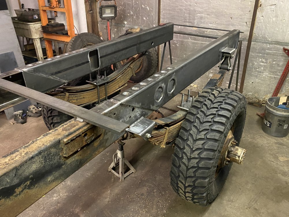
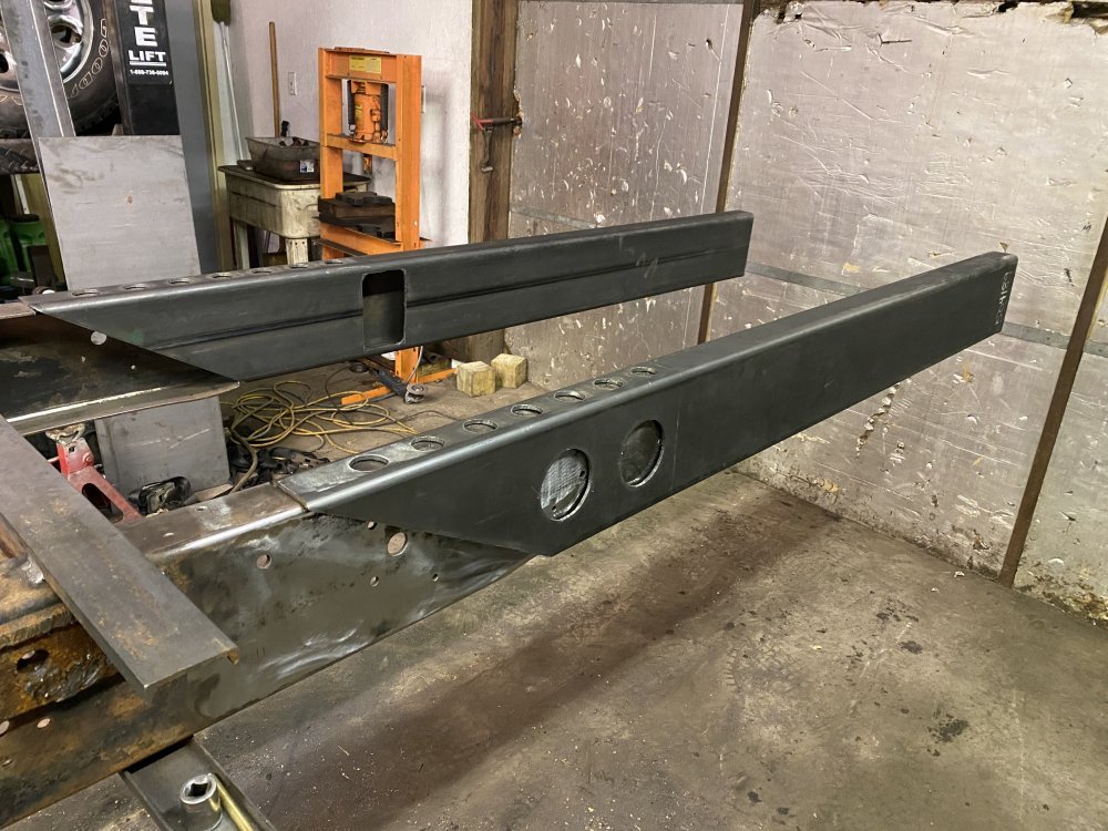
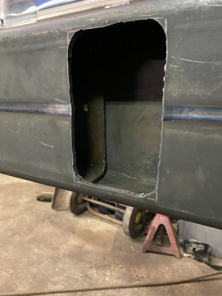
I was busy this weekend so I didn’t get anything done those days. Tonight I finished fitting the second rail and then added access windows to both rails so I’ll be able to add a weld bead at the interior seam in addition to the exterior ones. I’ll clean the edges of the window up with a carbide burr and smooth the radii in the corners to reduce stress risers.

82A661F0-B4DF-4EA7-B284-0EEB122A52B9.jpeg3496F978-A4F9-442E-BB3F-E4F547FB7A7C.jpeg
 
I was busy this weekend so I didn’t get anything done those days. Tonight I finished fitting the second rail and then added access windows to both rails so I’ll be able to add a weld bead at the interior seam in addition to the exterior ones. I’ll clean the edges of the window up with a carbide burr and smooth the radii in the corners to reduce stress risers.

View attachment 79447View attachment 79448
Will the window panes be welded back into position ?
 
Will the window panes be welded back into position ?
I keep going back and forth on that. I thought I was set on leaving it open so I could easily inspect the weld, but after seeing the opening I'm not sure I like leaving it open - even if I bolt a cover over it to keep junk out, I'm still not sure I like having the opening there. I am planning to box the entire frame because I'm concerned about the frame twisting with the dump bed in the up position and on some uneven terrain. I'm also concerned that if I only box it partially, that the place where I stop the boxing then becomes the part of the frame with the highest stress, so this has led me to the decision to box the entire frame. Now if I was to leave that window open, that feels like a huge opportunity for stress to concentrate in a twisting scenario, and I don't like how that feels in my head. So with all of that said, I think I'll be welding those windows back in place once the inside weld seam is complete.
 
Problems not having a boxed frame-what you mentioned and more. Twisting, bending, racking,etc.

Problems with boxed frame:
Cost more, Added weight, No crumple zone in a crash.

It’s always a trade off. Wife and kids not in it with you doing 60mph down the hiway- deciding is easy: fully boxed.
 
Progress has been slow the last couple weeks due to runs for parts & tools and also some house work, but today I finally had a full day and made some nice progress.

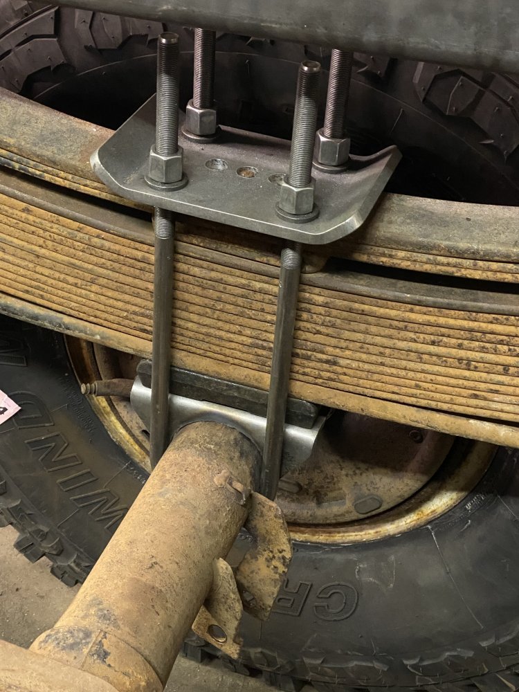
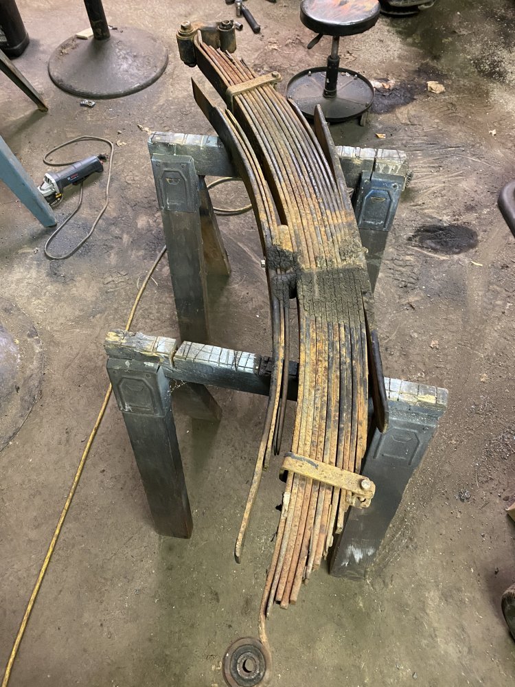
Prior to today I cut the spring perches off the axle and cleaned the tubes up. I also removed the factory bushings from the leaf springs, installed the ORD poly bushings & HD hanger and then started mocking them up. Man, these springs are heavy!!

0BA8C891-F99F-46AA-9DAF-DD555D844AAD.jpeg0DB0F6AC-490A-46B5-88AC-EBA6E2D6DF71.jpeg

I put a GM 1-1/4” cast iron lift block in the stack to give myself some easy ride height adjustment in the future……because I have the frame level right now, but I’m confident the front will settle more than the rear once the truck is complete, but I don’t know how much for sure at this point, so I’m doing this to make it easy to adjust once the truck is all together.

5D082266-A185-4DE7-A87F-205E3F2DA7F9.jpeg

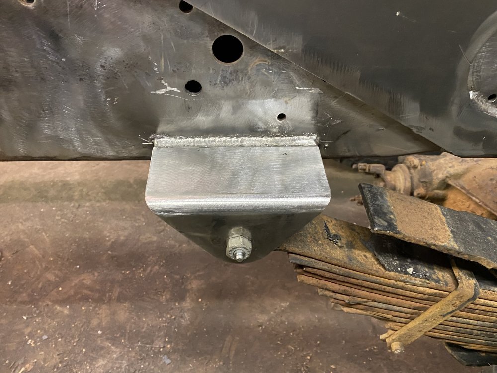
With the spring in place I could finalize my spring hanger plans. I got some 3-1/2” square tube with 1/4” wall and used that to make the hangers. I have the hangers in place, but not finished - I need to add gussets to them so they have adequate support. I’m going to go get some pre-made gussets from Alro on Monday because they have them cut out of cold rolled, which will be nicer to work with than the hot rolled I have here.

55A205C3-FD7C-45CA-8044-92B8511199B0.jpegF5F523D9-1EEC-4FC3-8D69-5B46FE562BF5.jpeg2C5331CA-BF9B-459F-8C53-6F6E87A97C2C.jpeg

I had a little time left so I started working on boxing the frame. Once I have the frame boxed I can add some crossmembers and then remove the jack stand and temporary crossmembers.

B8E87473-D166-4B2E-AD89-5F7C5FE9BDCD.jpeg

I won’t be making any more progress tomorrow, but I’m pleased with what I got done today.
 
I didn’t, but I’m thinking I will when I take it apart when mockup is done.
Be a good plan to do that.
Give You a chance to scrub them up and reassemble all nice and clean.
Those white teflon cushions would be nice between each spring but not necessary.
Only about four inch long and as wide as the spring.
 
Back
Top