smokymtn65
Well-Known Member
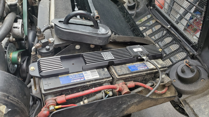
I haven't check rpm , i will try this weekend, i drilled and tapped my crossover for the fan sensor.

Follow along with the video below to see how to install our site as a web app on your home screen.
Note: This feature may not be available in some browsers.
Use your tech2, under special functions you can adjust the idle rpm's just for testing purposes.WOW didn't realize I had done this 3 years ago. Anyways I checked the fan speed vs pulley speed this evening. As far I can tell they are the same speed. At idle pulley was reading 870ish fan 480ish. With it engaged the fan was the same as pulley. Had my boy try to hold a steady 2k rpm and checked it then, pulley was 2370ish and fan was 2370 ish. Wish there was a better way to hold engine speed steady. Plus if your hand wiggles a little bit readings bounce around some too. There you go Will even after 3 years it's still the same pulley speed.

Hello All,
I've collected all of the parts to try this out on my H1. As ak diesel driver undoubtedly knows, here in Maine the colder ambient temperatures delay the onset of the thermo clutch and my temps spike up close to 220 before the fan engages - and with a brand new P400 installed, I don't want to risk another "oopsies". Until I get the body lift and intercooler all sorted out, I need a more aggressive fan. To my knowledge I'll be the first H1 that tries this.
My question was related to wiring, I see ak dd said he used the red and green wires on the clutch, but I'm not sure how they're actually connected. The controller has an orange 12v out and a blue12v out, and I'm guessing that only one of those is needed for the clutch, but then where does that orange wire go on the pin out for the clutch? Red? Green? There are three other wires as well- which seem to be related to reporting fan speed to the ECM (something I don't require). If I was a bettin' man, I'd guess that the red was the 12v+ (orange from the controller) and the green goes to ground but I just wanted to confirm.
Try as I may, I can't seem to find a pinout for the clutch harness.
Thanks in advance!
Hey there, I just installed this setup on my K3500, but have yet to drive the truck. You are correct on your wiring. Fan clutch Red is + and fan clutch Green is ground. Both Orange and Blue on the fan controller are outputs. I used the Orange to go to the Red on the clutch. I used the Blue to go to an indicator light in my cab so I can see when the controller is commanding the fan clutch to engage. The other 3 wires on the fan clutch are unused. Good luck with your install!
Thank you for confirming! I've got a similar plan in mind with an ON-OFF-ON switch in the cab. It'll be Auto(sender controlled), Off (for water fording) and On. The LED on the switch will be fed by the blue wire. I'm going to splice the "Always On" wire into the AC-on wire on the controller. The 12V power from the battery will be fed through a relay controlled by the switch as well. When the OFF is selected, I'm going to have a warning horn sound under the dash (kind of like the sound you hear when you engage the blower on inboard marine engines before you start them). This way the nut on the wheel won't cause the engine to burn up accidentally after crossing the river.
Hey Maugan, when ya do the install, add one wire in your self made harness that you don’t connect yet. Go from the control relay to the switch on the receiver dryer. Just leave it there at first and don’t connect to anything yet. Get the system in and working, then later it is ready for you to swap out the original one for a trinary switch and tie into the relay to have your a/c turn on the fan when it needs it.
But I say do that one afterwards as it’s own 1 day project because you’ll want to have it all adjusted for the engine needs regardless of a/c first. Then to add the switch you have to evac and recharge the refrigerant. Then its just a couple connections for the a/c.
Are you gonna DIY or have MM do it for ya?
Take lots of pics- it will help others along the way.

NOYup thats in the cards Will. In fact the "ON" switch position will just be spliced into the AC wire on the controller somehow - without risking turning on the AC
For the AC on wire would you just go for the AC Compressor clutch wire (as it states in the controller instructions or off the dryer harness?
Ok ok Ok Uncle Will! I'll get the trinary switch. From your post on that thread I think you're talking about this one on top of the dryer.NO
That is the point of the trinary switch. It tells the fan when to turn on by when it will help- having it on outside this perimeter is wasted energy. Rather than reposting it all here, read page 29 on this thread, and watch the videos.
1994 K3500 extended cab dually
Nice choice in buttons. Looks like a squeeze to get them both on that little plate. Some careful drilling there. I'm guessing that the LED is connected to the same side of the relay as the fan, or fan clutch in this case? If you push the button while the temp controller is already commanding...www.thetruckstop.us
")