• Welcome to The Truck Stop! We see you haven't REGISTERED yet.

    Your truck knowledge is missing!
    • Registration is FREE , all we need is your birthday and email. (We don't share ANY data with ANYONE)
    • We have tons of knowledge here for your diesel truck!
    • Post your own topics and reply to existing threads to help others out!
    • NO ADS! The site is fully functional and ad free!
    CLICK HERE TO REGISTER!

    Problems registering? Click here to contact us!

    Already registered, but need a PASSWORD RESET? CLICK HERE TO RESET YOUR PASSWORD!

Pseudo-Resto 96 K-1500…Um, when was this a good idea?

Even simpler Paul is to mix dish soap and water and use a pump window cleaner bottle. Tested thousands of welds this way. Only need about two pounds of air pressure.
Thanks. I didn't see this post until I had given it a test run on my -10 AN turbo return line. Proof that great minds think alike, that's just what I did tonight. I have a bottle of water mixed 10:1 with Dawn Dishsoap that I use for clean up. Worked great.
The only leak I saw was at the Air Pressure Stem inserted into the test plug. Ran it up to about 40 PSI it turns out. Too much but the line handles 60 psi on cold starts. IMG_0889.JPG
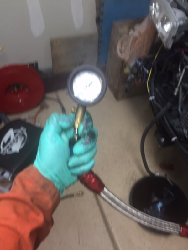
Admittedly, the picture is staged because it is too much to hold all in one hand but, it gets the point across.
 
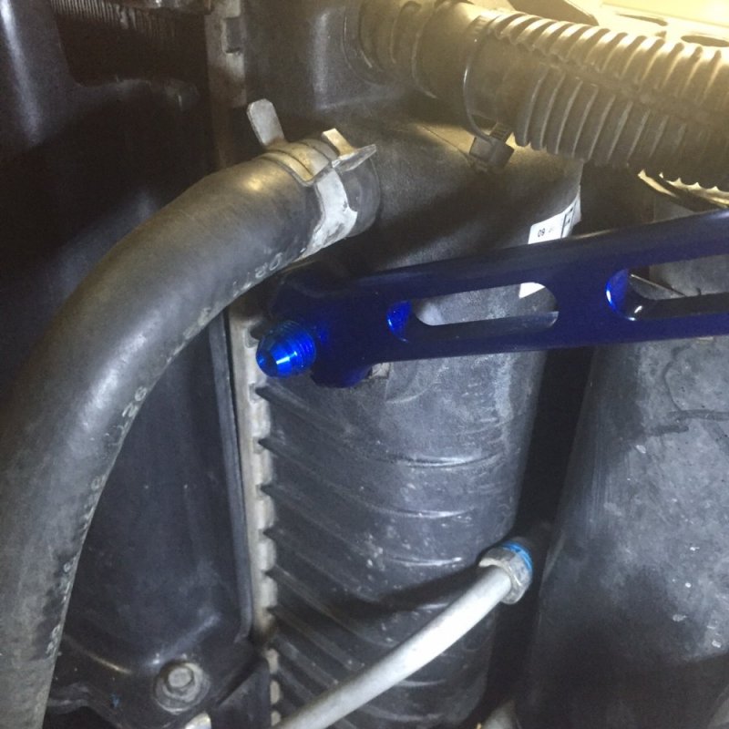
Short night tonight. Decided to just remove the transmission Auxiliary Cooler and Radiator lines and insert the fittings to ensure everything fit. The first task was to find the fittings as I’d moved the box...somewhere… Sure enough, right where I left them.

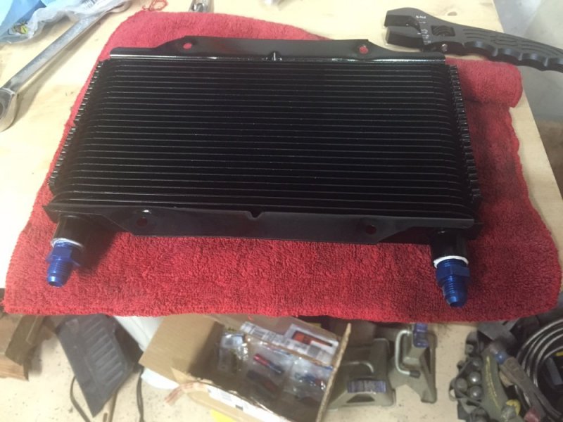
Auxiliary Cooler lines were first. After removing the lines and then the cooler to let it drain somewhere other than all over the floor. I brushed it down, blew compressed air through it etc. to get out all the bugs. Degreased it and rinsed it all down and set it off to dry.

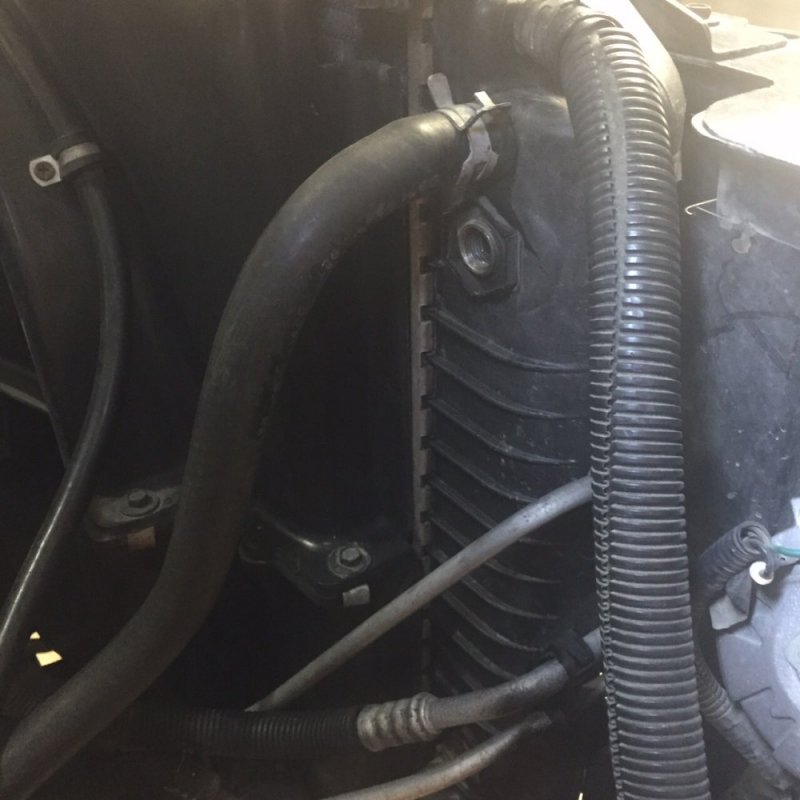
Next I removed the lines from the Radiator and did some cleaning up with degreaser to ensure the pictures looked good.
IMG_0880.JPG
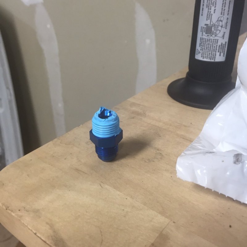
After test fitting, the fittings were wrapped with pipe thread tape.
IMG_0886.JPG

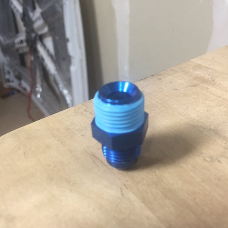
The excess tape was trimmed back from the inversed flare to ensure none of it got in the way of the seal or the fluid flow.
IMG_0887.JPG

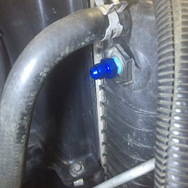
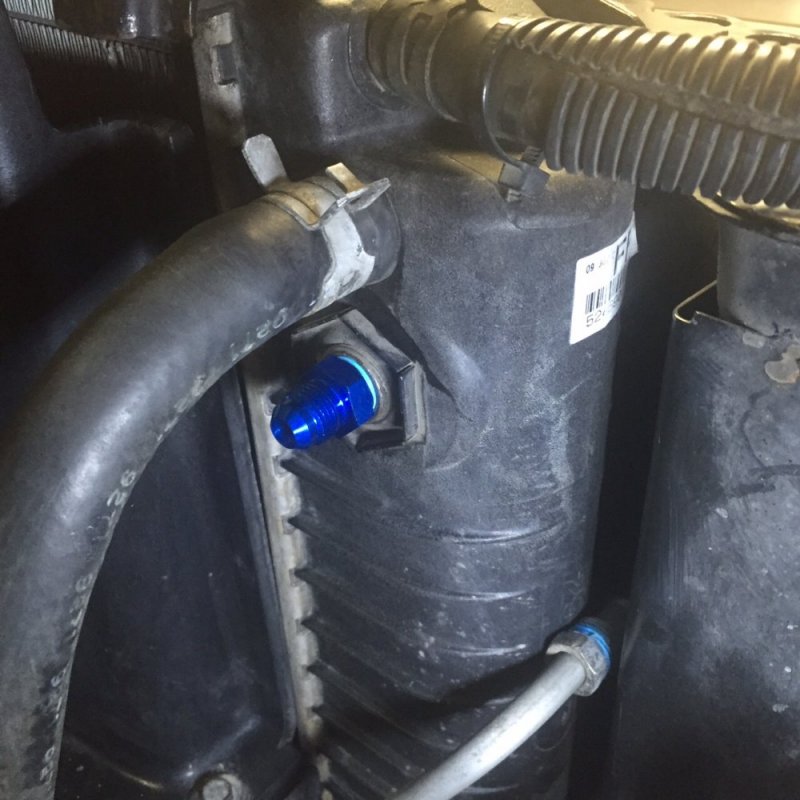
Fittings inserted...
IMG_0881.JPG
...tightened down...
IMG_0884.JPG

...and now awaiting the construction and fitting of the new lines.

IMG_0885.JPG

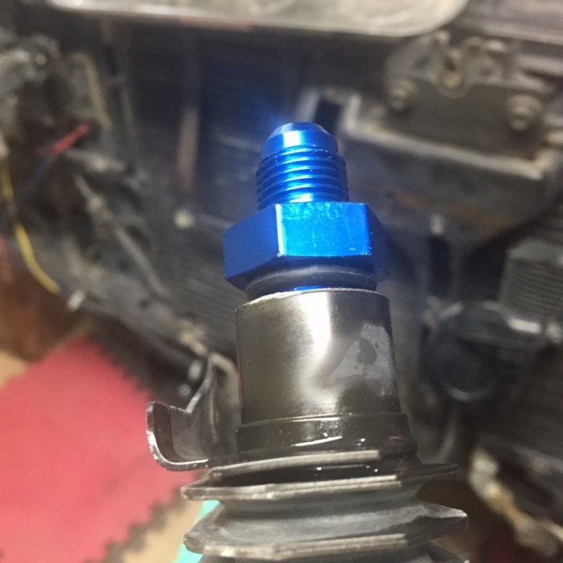
For the Auxiliary Cooler, I test fitted the ‘Boss’ 5/16-18 s just for grins and giggles. They threaded in as loose as you’d expect, and rattled regardless of seating against the O-rings, by hand. I backed them off to show the o-rings.
IMG_0879.JPG

I knew from Leroy’s observations that the correct fittings were the 3/8 NPT units anyway and those two fittings were the few parts of the original order that I had gotten correct.

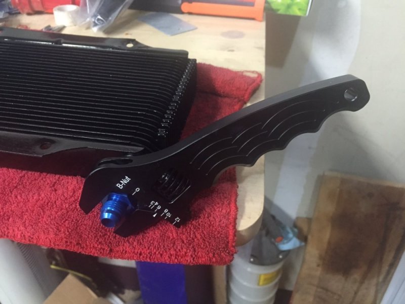
After painting the cooler and letting it dry (while working on the radiator fittings) I applied some thread sealer and using the AN Adjustable wrench, tightened them down nice and snug.
IMG_0890.JPG

IMG_0891.JPG
They’ll remain on the bench overnight while the sealer sets up and the paint fully dries.
 
Just being picky but you don't need tape on the inverted flare. The sealing is at the flare surfaces. Tape won't hurt anything though.
Looks good.
 
Just being picky but you don't need tape on the inverted flare. The sealing is at the flare surfaces. Tape won't hurt anything though.
Looks good.
Kinda figured I didn't but, when the motor was swapped I put in the radiator 635 had given me and despite tightening the fittings, a couple of times for the upper one, it still weeped fluid until being taped. Better safe than sorry
 
Just a heads up for everyone, air tests shouldn't exceed 5 psi as it can be like a bomb. Liquids are used above 5 psi. With those small lines you were likely safe enough.
 
Yeah, we test components for petrochemical plants at 15 psi max when only air and bubble test. For at home testing you can raise pressure depending how much volume is there. An example would be your coolant system at 20 psi max, but I go 17, as the cap is 16.
Nvw has the right idea, 5 psi is a good safe test.

Anything beyond that requires hydrostatic testing and is deadly force. As is the concussion forces alone will end you for being in the yard.
 
I can't remember which governing body "ASTM, ASME, CWB" ect, but up here 5 psi is max in the oil patch for piping or vessels using air.
 
So my homemade potato cannon that I built from PVC and aired up to 150psi might have been a little bit dangerous?

It was fun though, I built a metal dart for it that would easily penetrate a Chevy bed side from 50 feet away and spit a golf ball over 300 yards. ;)
 
I would like to take the opportunity to thank you guys for the safety warnings. Points taken and advice headed...except for you Leroy...You get the prize for 'serves as an example for others.'image010.jpg
 
So, today I got the lines for the Transmission out (Hot Side) to the Aux. Cooler and from the Cooler to the radiator (lower connection).

I learned that the drawings from my manuals for the transmission were a bit off so, I’ll have to update my ‘instructions to self’ that I wrote up (with lots of pictures) so it will be correct next time I refer to it. I do this pretty much for every project so I have a visual reference and am as familiar with the procedure as I can be. I’m a coward at heart and not too intuitive so it helps to have worked through it in a paper drill.

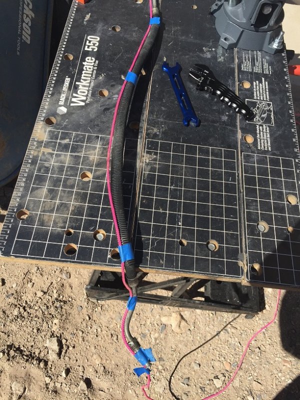
I removed the lines and used them for measuring the new ones.
20150918-004.JPG

One mistake I made was not identifying a standing and running end to the line I was using to get the length for the new lines. My ‘end’ mark was about mid-way so I had to redo the first one to make sure I wasn’t ‘measuring once and cutting twice.’

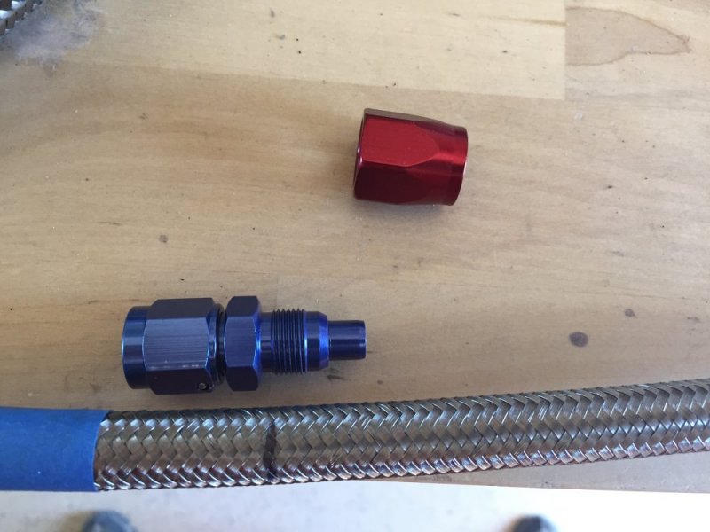
I measured from the end of the fitting to end of fitting so when I marked the braided line, I then set the fitting up and marked the actual end of the hose.
20150918-005.JPG
I’ve got a feeling I’ll have plenty of line to secure under the chassis given the factory stuff have a lot of tight bends the braided lines won’t be making.

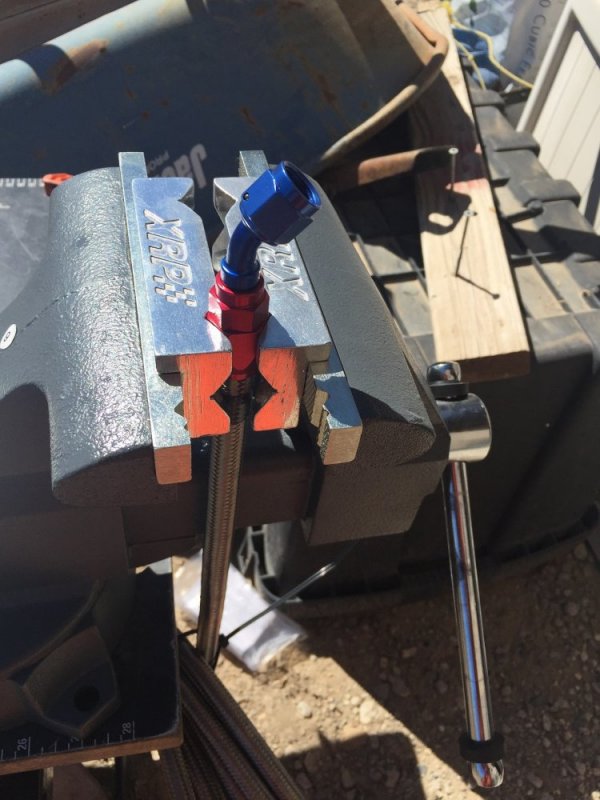
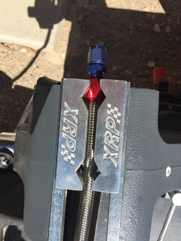
Using my new bench vice to hold the lines, the anodized fittings are held in the XRP vice adaptors to avoid marring the finish and then snugged down.
20150918-006.JPG

Nice thing about the Vice adapters is that they allow for securing the lines either vertically or horizontally. A nice feature.
20150918-007.JPG

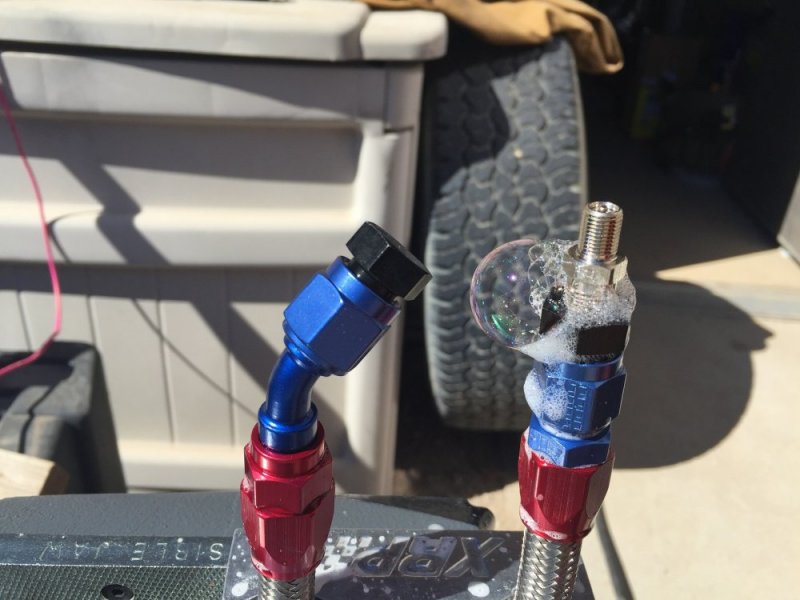
Then, following NVWs advice, a low pressure test of the finished line. The only leak noted was around the valve stem. I used the dust blower nozzle to clear away the solution to ensure there wasn’t any other leaks combined. Next set of lines I simply squirted, sparingly, a small amount of the soap and water solution on each point where a leak would manifest itself.
20150918-008.JPG

Auxiliary Cooler replaced and plumbed up.
20150918-12.JPG
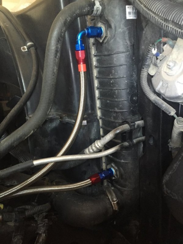
What the Radiator will look like when the return line is done. Truth in advertising, this picture actually has the transmission feed line's end (90* elbow) attached to the radiator to give an indication of what the finished set up will look like. I still have one more line, the Return line from Radiator to Transmission, to build. Needed different hose ends...see below.
20150918-013.JPG

I decided against using -6 AN 90* 1/4" NPT elbows at the transmission for the feed and return lines because:
1) Clearance issues around the dipstick tube for the output line was a concern, not sure it would even thread in, let allow for the hose to connect up.
20150918-010.JPG
2) It seemed that when I was snugging down the fitting I had on the return side, the final position would be somewhat off axis to the front

3) When I get the FS-2500 sorted out, I’ll need to redo some of the line routing on the return side anyway and using the 90* elbows to the -6 AN / ¼” NPT straight adaptors would make that a lot easier.

So, back to the internet. I ordered the parts tonight, again from Summit, along with more hose (amazing how fast 20’ gets eaten up, especially with the FS-2500 project looming. Web page says it ships tonight. These guys are great. If I get the parts tomorrow, I'll wrap it up. If not, I've got an air hose reel that needs to be mounted and plumbed. Got it for Christmas...procrastination is a talent I apparently have.
 
No delivery today and I don't feel like running round trying to find the fittings locally.

Instead I decided to spruce up the transmission a little while I wait. The pictures I posted were a little embarrassing.
DSC_3172.jpg
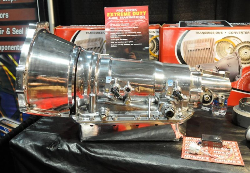
Ok, seriously now, I was updating my 'manual' and googled '4L80E' to get better pictures and this was in the results. I don't want to hear anymore talk about how clean my motor etc. is. I'm a @#$%^&* rank amateur-wannabe-poser compared to this guy.
 
That is a perfect example of a utter and complete waste of time and tooling! Unless he put in a glass floor no one is going to see it. Of course it could be a "useless" show/sales piece never intended to be installed...
 
Interesting you posted that. I just pulled a trans from a 98 Savanna van today w/6.5.
It has a tail housing made for a driveshaft to go into the trans like an old th400 and your picture.
I did not know they came factory like that. Only seen the pillow block type. Maybe the vans just remove the block? That what I did on my Chevelle so I could run a regular driveshaft.
I know the one in the picture is to retro fit into?? as it has the cable drive for speedo.
 
:banghead::banghead::banghead:
I just don't get it!
I received the -6 AN - 1/4 NPT fittings for the transmission's IN and OUT ports.
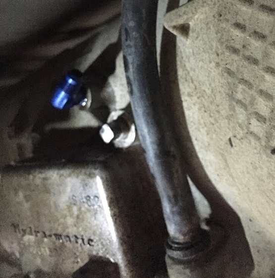
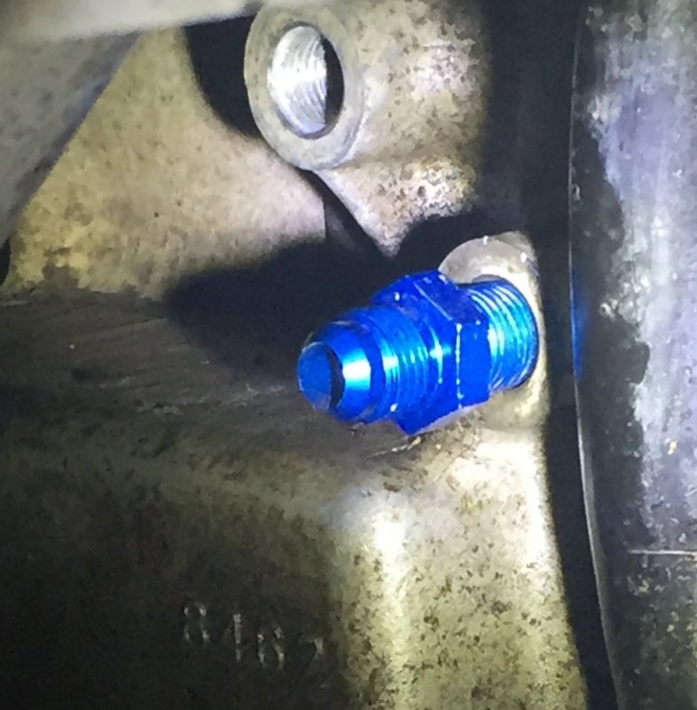
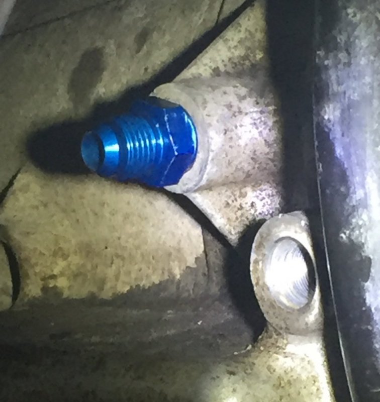
Both are the same 1/4 NPT but the fluid OUT port want accept either of the new fittings for more than ONE turn into the transmission...by hand.
The Fluid IN port accepts them both, by hand, pretty darn near flush with the case. I tried them both in both ports but neither will go past one full turn at the OUT port.

Picture. Out port with new fitting.
FullSizeRender.jpg
Picture. IN port with new fitting.
FullSizeRender (1).jpg

I removed the OEM fittings from their respective tubes and tried them both of them in both the IN and OUT ports and both of the OEM fittings thread in easily for several turns regardless of which port they are tried at.

The new fitting placed at the "IN" port threaded in and when tightened up, it went flush with the case before it stopped.
That doesn't seem correct either.

The side of my brain that needs to be ignored says, 'just use thread sealant and an O-Ring on the "IN"' port and for the "OUT" port...'go for it (with the new fittings) they're NPT and are supposed to tighten up.
The other part of my brain that I hate to listen too says to "take the OEM fittings to a hydraulics shop and get it sorted out before you split the case." Going to a hydro shop tomorrow...never ends...I've got enough fittings laying around to open my own shop and none are correct...

On Edit: I googled "4L80E fluid line fittings" and the results are all 1/4 NP S. What's NPS besides the correct thread!
 
I gu
I just did the same google search you mentioned and the fittings that came up said they were nps. I don't know if that is correct.

http://www.summitracing.com/int/search/part-type/transmission-line-adapter-fittings
I guess I'll find out. I ordered the Fragola's. Those were the only ones that popped up with the initial "NPS" search query at Summit. I saw the Russells and others with the crush washers at Jegs but thought that was overkill. The '4L80E' fittings with the extended internal fitting are for the 'rear port' on the transmissions that put the output line all the way to back. I noticed that depending on the application, the 4L80s have different line configurations. Given that my lines don't protrude to the inside of the transmission housing, I opted out of that set up.
Thanks for the quick replies. Very much appreciated.
 
Here we go again!
Actually, I was wondering if they might be 3/8 something other than NPT but I couldn't recall if I had an extra 3/8 inverted flare laying around. Given the Google Search and no IF listings on the 'transmission fittings' listings at Summit or Jegs, I'm really hoping they are 1/4" NPS. Still, it wouldn't be the first time this week I've been wrong...again.
 
Back
Top