The best, Banshee controller ... The fleese doesn't compare from what I've read.

Navigation
Install the app
How to install the app on iOS
Follow along with the video below to see how to install our site as a web app on your home screen.
Note: This feature may not be available in some browsers.
More options
-
Welcome to The Truck Stop! We see you haven't REGISTERED yet.
Your truck knowledge is missing!
- Registration is FREE , all we need is your birthday and email. (We don't share ANY data with ANYONE)
- We have tons of knowledge here for your diesel truck!
- Post your own topics and reply to existing threads to help others out!
- NO ADS! The site is fully functional and ad free!
Problems registering? Click here to contact us!
Already registered, but need a PASSWORD RESET? CLICK HERE TO RESET YOUR PASSWORD!
You are using an out of date browser. It may not display this or other websites correctly.
You should upgrade or use an alternative browser.
You should upgrade or use an alternative browser.
Final details for my "Twisted" P400 build
- Thread starter Twisted Steel Performance
- Start date
Steed Dolan invented and perfected it, then sold the rights to the purple turbo folks and now is on there contract list for other stuff.
DieselAmateur
She ain't revved 'til the rods are thrown...
What are all the 45* and 90* fittings on the heads in the valley side of the engine for Chris?
Will L.
Well-Known Member
3 points! I been waiting for someone to ask that! One of the other cool things I am waiting to see how it goes on his engine.
I can’t tell- thats up to Chris to share or let others figure out- but he has a fun idea there...
I can’t tell- thats up to Chris to share or let others figure out- but he has a fun idea there...
They are for coolant flow between the valves and when plumbed in will lead to the water crossover. If yoy look at my past pics of a head cut apart, that passage is a dead hole and air is trapped water will sit, this will allow flow and all the air to be purged from the system...What are all the 45* and 90* fittings on the heads in the valley side of the engine for Chris?
dbrannon79
I'm getting there!
Thats a nice addition! I wonder how much better cooling performance just that modification will bring.They are for coolant flow between the valves and when plumbed in will lead to the water crossover. If yoy look at my past pics of a head cut apart, that passage is a dead hole and air is trapped water will sit, this will allow flow and all the air to be purged from the system...
jrsavoie
Recruit
Considerable, would be my first guessThats a nice addition! I wonder how much better cooling performance just that modification will bring.
dbrannon79
I'm getting there!
I wonder how hard that would be to add those ports without pulling the heads! or would the factory intake interfere with it. problem is knowing exactly where the tubes are would be the problem when drilling and tapping. then for guys like me, which direction the coolant would be flowing as to the best spot to connect them to for flow into or out of the head!
never the less I bet it would greatly help with head cracking especially on the #8.
never the less I bet it would greatly help with head cracking especially on the #8.
There are factory plugs in that location anyways, they are too big for 1/8ntp so they need in larged for 1/4ntp. I doubt it would be easy on the truck and I don't know if there is room under the stock intake.
dbrannon79
I'm getting there!
I wonder.... lol my gears are turning in my head again haha... a 1/4" brass street 90 pointed towards the front of the engine at the rear ports followed by 1/4" street tee's all plumbed together to end up with two ports up at the front of the engine, one on each side. as long as the ports aren't directly below the air intake ports of the head a stock intake might could be made to fit or modded. even a 1/4" thick spacer plate under the intake to raise it a hair or two might be the trick!
MrMarty51
Well-Known Member
Some more great mod ideas coming to fruition.
That head cooling mod might be easily obtainable even if it was only to the number 8 cylinder position.
That head cooling mod might be easily obtainable even if it was only to the number 8 cylinder position.
Well it's not a bolt on thing so I doubt it would be done by many. Kinda like folks changing to a screw on w/p , why not save that money and trouble and just use the same w/p in the 4 bolt version and not all the extra cost of blade, cut the shroud, etc...
DieselAmateur
She ain't revved 'til the rods are thrown...
Very cool Chris! Impressive as always
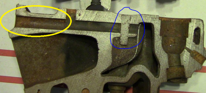
Is the dead hole the cavity immediately to the left of the injector & swirl chamber in this pic? Only one I could find from your head comparison thread

Is the dead hole the cavity immediately to the left of the injector & swirl chamber in this pic? Only one I could find from your head comparison thread
yes....
dbrannon79
I'm getting there!
Chris, I see the two head sections where one is not threaded and the other is, the one that's threaded seems to have that cavity blocked off where the other isn't. also I assume that tee part of the port comes from a water passage in the block?
just curious what the differences are on the two cutouts and what the cavity was meant for.
The top pic is a p400 head, the lower is a late gm/gep head, the plug seen is a casting change gep made to try and strengthen and slow the cracking between the valves.
SnowDrift
Ultra Conservative. ULTRA!
From this image, does this mean the GEP head doesn't have coolant going into the cavity to the right, but the P400 does? What I mean is, is the area indicated in red void of coolant?

Still trying to understand the differences between the P400 and GEP heads. Maybe there is a write-up on it in one particular thread that I missed?
Still trying to understand the differences between the P400 and GEP heads. Maybe there is a write-up on it in one particular thread that I missed?
Attachments
Yes you are correct.
ak diesel driver
6.5 driver
Which I believe is why he did the hoses, to get any trapped air out plus any circulation at all would be a benefit.
dbrannon79
I'm getting there!
I got a chance to look at the 6.2 I have on the stand the other day. it seems like there is enough room under the stock turbo style intake for fittings to thread into the head. this might be one thing I would like to add on, once I get around to fixing up the donor 6.2 for my truck.