• Welcome to The Truck Stop! We see you haven't REGISTERED yet.

    Your truck knowledge is missing!
    • Registration is FREE , all we need is your birthday and email. (We don't share ANY data with ANYONE)
    • We have tons of knowledge here for your diesel truck!
    • Post your own topics and reply to existing threads to help others out!
    • NO ADS! The site is fully functional and ad free!
    CLICK HERE TO REGISTER!

    Problems registering? Click here to contact us!

    Already registered, but need a PASSWORD RESET? CLICK HERE TO RESET YOUR PASSWORD!

A Rat Munched My Wires

Jay-Bee-Kay

New Member
Messages
8
Reaction score
5
Location
California
I have an '88 Silverado K-1500 and it's been parked for 13 years, because I refused to junk it after my wiring was damaged.
Now I am finally getting around to repairing it after all this time.
It's a California truck which makes things more interesting. So I've decided to convert it to propane, which means it will be smog exempt, so compliance will not be an issue in this case.

The engine is a 5.7 and the trans is a TH 700R4.

I'm not having any trouble with engine wiring. The thing I'm having trouble with is the brake light / TC clutch / cruise control switch.

I bought a Haynes manual because it looked like it had a good schematic and chassis electrical section, but I am finding out that there is very little in the manual that is applicable to my situation.

The thing that I could really use is a good schematic that has info that applies to my wiring. But if I can't get a schematic that matches, then maybe someone could talk me through it..

The wiring suffered it's first blow when a rodent ate through some of the insulation in 2005.
I converted it to a carb and ran it for a short time but the EFI fuel pressure was more than simple hose clamps could tolerate and a leak started which resulted in a fire... Which further complicated an already challenging problem.
Anyhow - I have most of it figured out for the conversion, but the brake light / torque converter clutch wiring is giving me nightmares.
I plan on deleting the cruise control.

If someone could refer me to a schematic or a good electric manual that covers chassis wiring, that would be extremely helpful.

Thanks in advance!

... Hope you are all enjoying these long summer days


PS - I will include some pics as soon as I figure out how to do that
 
Last edited:
If you've already converted it to a carb, the buy one of the 700r4 lockup kits from summit and be done with it. Iirc the brake switch supplied power to the plug at the trans for lockup, and the ecm provided the ground signal. It's a very basic control system.
 
I do have a 700R4 lock up kit
The ecm is gone. Along with it went my speedo. So I bought an aftermarket gauge set and I'm fabricating a new instrument panel with some analog gauges.

I'd like to see just a basic schematic for any typical tail /stop setup with dual filament bulbs, hazard flasher, turn indicators.


Also:
There is a rectangular switch with a brown wire and green wire that is operated by the brake pedal.
The same brown and green wires go to another switch that is also operated by the brake pedal, and when the pedal is pressed down the circuit is broken.
I am assuming that this is the cruise control shutoff with a redundant switch.
Am i correct about this?

Without a diagram, I'm playing a guessing game

Thanks for the replies BTW it's good to be getting some feedback on this. I lost all my momentum for a while.
 
Last edited:
Replace the brake switch as they fail often then continue troubleshooting. Note the "adjustment" of the switch may also be a factor. Quick and dirty is unplug switch and brake lights go off if they are stuck on. Not real clear on the exact issue you are having with said switch.
 
Things are shaping up. I looked at the schematics on Wilsonelectric, and at least there is something there that comes close to matching my wiring.
I've been lucky so far and the repairs were simple and everything works. but I still can't claim to understand the system.
I've been busy getting my hands dirty for the past couple days and haven't been online, but I have some questions on the brake switch.
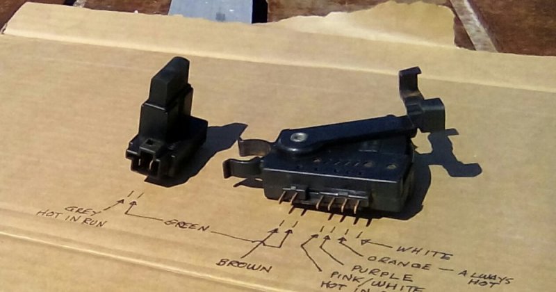
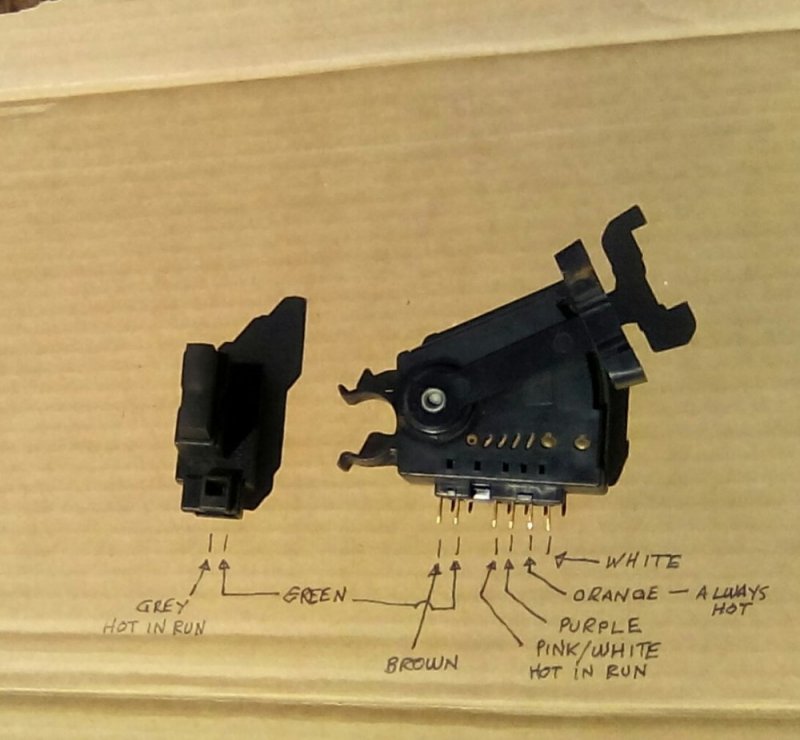
Only the orange wire and the white wire activate the brake lights. There's a pink/white and a ppl - also a green and a brown, for a total of 6 wires.
I have an aftermarket relay for the TC clutch, So I ought not to have to use the TC clutch wiring that is a part of the brake switch.
I'll try to post some pics this afternoon.

Thanks for taking the time to help out
 
I bought a wiring kit that has a relay that opens the TCC circuit when the brake lights go on.
I'm guessing that originally the signal to open the TCC circuit came from the ECM... But there's another switch that accompanies the brake light switch that opens when the brake is applied, so maybe the signal didn't go through the ECM
 
I took shots at a couple different angles for clarity. I hope they are legible.

The brown, grey, green circuit is open when the brake pedal is up and closed when the pedal is depressed.
It appears to be a redundant switch. It is ON when the key is in RUN

The orange, white circuit is open when the brake pedal is up and closed when the pedal is down. It is always ON

The pink/white, purple circuit is open when the brake pedal is up and closed when the pedal is depressed. It is ON when the key is in RUN.

It seems like the only circuit I really need is the orange and white circuit, because I have a wiring kit that has a relay that opens when the brake is applied - disconnecting the TC clutch.

I'm sure that there has to be someone else out there who is familiar with these circuits - LOL - There were only a few million of these trucks produced...

Before I go any further I'd like to find out more info on what the intended purpose of the circuits was originally.
Also, is there a relay on the brake light circuit, or does the wire from the switch go directly to the lights?

I have been referring to the schematic from wilsonautoelectric and it shows the orange - white circuit and the pink/white - purple circuit only.

Any clarification would be enormously appreciated!
Refer to my first post for specifics about year, model etc

Thanks for all the help so farIMG_20180715_160633_639.JPGIMG_20180715_160345_668.jpg
 
Last edited by a moderator:
Sure...
It isn't easy to make a long story short here, but I'll do what i can.
My '88 (5.7 K-1500) has been parked for 13 yrs. Things were going from bad to worse on it and I had run out of time to work on it, but I couldn't bring myself to have it scrapped. I just kept it in storage at a rental area... and this year I got news from the property owner that the storage/shop area will be selling, and I knew that it's now or never to repair it.
It needs a new engine and there was damage to the wiring because of rodent chew and later from a fire, which burned for less than 30 sec.
But I decided to convert it to propane, and to eliminate the ECM for purposes of simplification, and user serviceability.
I bought a Haynes manual because it showed a schematic, but progress came to a standstill when it was time to do the electrical work, because nothing from the schematic matched my wiring.
I thought that I was going to have a nervous breakdown with all the time this project was consuming and the slow rate of progress.

So the project of bringing my '88 is about 50% done with a couple months of summer remaining.
But with schematics from the wilsonautoelectric database in-hand, I am on a roll with the wiring phase of the project!

Thank you for the link to that site ! !

I will continue to post with updates as things progress.

For the time being all my questions are answered - Much Gratitude
 
Back
Top