
Navigation
Install the app
How to install the app on iOS
Follow along with the video below to see how to install our site as a web app on your home screen.
Note: This feature may not be available in some browsers.
More options
-
Welcome to The Truck Stop! We see you haven't REGISTERED yet.
Your truck knowledge is missing!
- Registration is FREE , all we need is your birthday and email. (We don't share ANY data with ANYONE)
- We have tons of knowledge here for your diesel truck!
- Post your own topics and reply to existing threads to help others out!
- NO ADS! The site is fully functional and ad free!
Problems registering? Click here to contact us!
Already registered, but need a PASSWORD RESET? CLICK HERE TO RESET YOUR PASSWORD!
You are using an out of date browser. It may not display this or other websites correctly.
You should upgrade or use an alternative browser.
You should upgrade or use an alternative browser.
6.5 non turbo diesel 4L80E chevy p30 StepVan
- Thread starter Brenttt
- Start date
dbrannon79
I'm getting there!
Welcome aboard.
Have you connected a scanner to read codes? some trans codes my set but not turn the ses light on.
Have you connected a scanner to read codes? some trans codes my set but not turn the ses light on.
dbrannon79
I'm getting there!
what type of scanner are you using, also have you already checked all fuses and grounds. many problems arise simply from ground issues. I am sure others will chime in to help soon. tell us details on your rig and all that you have done so far leading up to and when the issue began.
Will L.
Well-Known Member
We need more details.
If this is a db2 injection pump, I would say adjust tps.
If this is a db2 injection pump, I would say adjust tps.
I’m using the OBD2 scanner this may require a OBD1 I changed the sensors on the side of the trans and checked the fuseswhat type of scanner are you using, also have you already checked all fuses and grounds. many problems arise simply from ground issues. I am sure others will chime in to help soon. tell us details on your rig and all that you have done so far leading up to and when the issue began.
dbrannon79
I'm getting there!
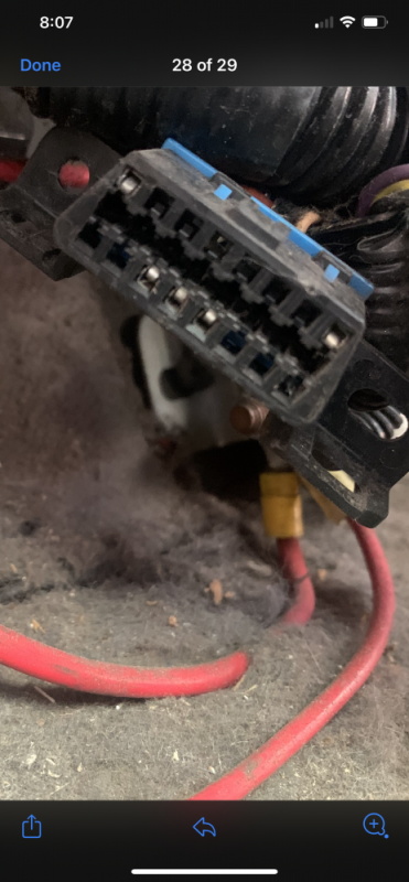
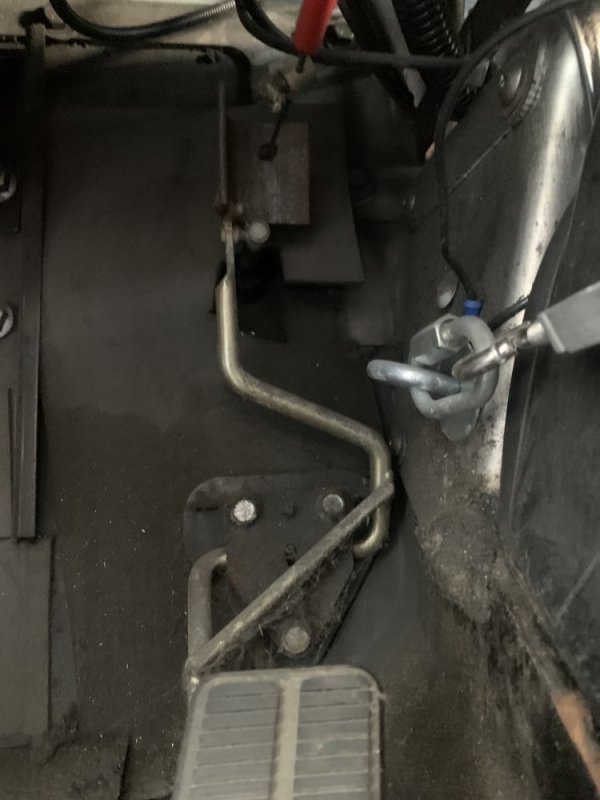
if you's is a true OBD2 system, you can use a test light and check for power and ground using the pinout diagram. pins 4 and 5 will be ground. pin 16 should have 12 volts at all times. since a stepvan can have anything in it for that year model, a simple way to check if you have a DS4 or DB2 pump would be to look at the accelerator pedal and injection pump. is there a mechanical cable attached to the pedal going to the pump or nothing but wires. the DB2 like Will mentioned will use a throttle cable. this style will only have a transmission controller and no engine controls.

- Staff
- #8
Need to know if it's a DB2 mechanical injection pump or the ds4 electronic pump. Each system is considerably different. And being a P30 chassis in 96, it may be the hybrid data coms that were used in a select few 96's that require a tech2 scanner.
if you's is a true OBD2 system, you can use a test light and check for power and ground using the pinout diagram. pins 4 and 5 will be ground. pin 16 should have 12 volts at all times. since a stepvan can have anything in it for that year model, a simple way to check if you have a DS4 or DB2 pump would be to look at the accelerator pedal and injection pump. is there a mechanical cable attached to the pedal going to the pump or nothing but wires. the DB2 like Will mentioned will use a throttle cable. this style will only have a transmission controller and no engine controls.
View attachment 68203
i’ll take a look at this tomorrow and see what I have in it there’s a picture of the OBD2
Attachments
dbrannon79
I'm getting there!
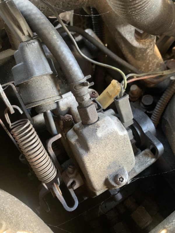
Take a couple of snapshots of the IP on the engine, @THEFERMANATOR will have more knowledge on this. looking at the available pins in your PCM connector, you only have one pin for data, pin 6 . as he said generic scanners won't be able to connect to this due to the pin arrangement and type of data bus.
Here are a few pictures also has a throttle cableTake a couple of snapshots of the IP on the engine, @THEFERMANATOR will have more knowledge on this. looking at the available pins in your PCM connector, you only have one pin for data, pin 6 . as he said generic scanners won't be able to connect to this due to the pin arrangement and type of data bus.
Attachments
-
 99A70FB0-9580-4F5A-B51F-80C50A7E034D.jpeg84.7 KB · Views: 12
 -
 18CD3E4C-2270-46A3-91B6-2CE2985BAA81.jpeg134.2 KB · Views: 13
 -
 633AE481-D680-4EB8-9106-F2E446ACE37C.jpeg134.2 KB · Views: 13
 -
 F43D0498-F1F0-4AE1-865F-A43880DAE272.jpeg134.2 KB · Views: 12
 -
 5E77A1C2-4D0B-4C28-B7D7-7B26705A8569.jpeg116.6 KB · Views: 12
 -
 611090D7-1482-4D62-B7C0-457CE4E541AF.jpeg84.7 KB · Views: 11
dbrannon79
I'm getting there!
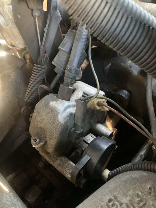
ok, you have a DB2 style IP. to correct the shifting on this truck, the throttle position sensor will ether need to be adjusted or replaced. it will be located on the IP near the cable linkage iirc. others will have more experience on this that know more about the DB2 pumps.
you can test the TPS by using a digital volt meter and probe the 5volt return wire and slowly pressing the pedal, the voltage should smoothly go from 0 to 5 volts with out any drop outs or spikes. But wait for Will or others with more knowledge to chime in. I have not had the luxury of working on a DB2 style truck.
@Will L. I think your a DB2 guy!
Will L.
Well-Known Member
He nailed it. 5volts at full throttle and smooth transition all the way down.
They rarely fail in my experience. And if you install a new one you have to adjust it just like the existing one, so break out the volt meter and a straight blade screwdriver.
The following is not for now, but ling term info.
You have db2, obd1 system. You will have a tcm (transmission control module) not an ecm.
Last edited:
dbrannon79
I'm getting there!
looking in those snapshots in his photos, it looks like the TPS is maxed out on adjustment in one direction. @Will L. would you know of a procedure to adjust one when it the TPS may have been moved or came loose? just thinking maybe there is a way to know more of less how to set one up with out knowing if it's adjustment might already be out of whack.
Will L.
Well-Known Member
yes it looke like someone installed it and either forgot to tighten after adjustment or just put it on and didn’t know.
It is always a 0.5 to 5volt reference. 5 volts at full throttle.
there is proper tooling to get it super exact, but 60,000 miles wear on a timing chain throws that into the why bother category.
@WarWagon shared a really simple method here years back.
It is always a 0.5 to 5volt reference. 5 volts at full throttle.
there is proper tooling to get it super exact, but 60,000 miles wear on a timing chain throws that into the why bother category.
@WarWagon shared a really simple method here years back.
I use a good digital voltmeter. I use pins to back probe the connector for ground and the wire that varies from 0.5V to near 5V. Key on engine off. Make sure the fast idle solenoid is disconnected. My sensors would never hit 5V at WOT: 4.XX V. At idle you want 0.5V or a little more: NEVER under 0.5V. 0.6V is fine. (You have +5V, sense wire, and ground.)
You rotate the sensor to adjust the voltage. Make sure it increases voltage as you open the throttle. It's possible to install the sensor improperly and not get the proper voltage range.
Measure it before you FK with it! This way you will know if it is the problem or not before making new problems.
The speed sensors on the transmission can be mixed up. You will need a scanner to see the input RPM. If the output RPM matches engine RPM at 0 MPH they be backwards.
The insulation at the junction to the harness for speed sensors also falls off these wires. Check for this aka shorted sensor.
dbrannon79
I'm getting there!
from what I gather from WW, they will be different. I circled your fast idle solenoid on the IP
I’m using the OBD2 scanner this may require a OBD1 I changed the sensors on the side of the trans and checked the fuses
Also the two sensors on the side of the transmission are they not the same? I’m assuming you’re talking about the wiring ?
In 1993 the input speed sensor and output speed sensor on the driver side are the same plug. IDK about newer years. These are two wire connectors. Their wiring off the transmission going into the harness bundle has insulation that fell off right at the bundle on a few pickups I have run across including a 454 powered rig. Bare copper shorts the sensor reading out. This is NOT the main transmission connector. You may also look at it for possible oil leaks at/in the main trans connector as oil is an insulator.
As mentioned the TPS looks like it was put on loose and worked itself to the end of the adjustment.