• Welcome to The Truck Stop! We see you haven't REGISTERED yet.

    Your truck knowledge is missing!
    • Registration is FREE , all we need is your birthday and email. (We don't share ANY data with ANYONE)
    • We have tons of knowledge here for your diesel truck!
    • Post your own topics and reply to existing threads to help others out!
    • NO ADS! The site is fully functional and ad free!
    CLICK HERE TO REGISTER!

    Problems registering? Click here to contact us!

    Already registered, but need a PASSWORD RESET? CLICK HERE TO RESET YOUR PASSWORD!

Project "Johnny Cash"

Will is right. It's hard to find a big enough electric fan setup to properly cool a diesel. And alot of the normal electric fans setups I've seen for c10s all block half the radiator off with two fans in each corner. I feel like it cuts off so much airflow through the radiator. A good mechanical fan and shroud can move alot of air and pulls across the whole radiator core. Most manufacturers have moved to electric fans on v8 gas trucks. But the diesels still gets a big mechanical fan. They need all the cooling they can get.

I had thought about the Dmax electric fan. But it won't with the square body radiator correctly.

I hadn't considered a hydraulic fan option. Though. I used to work on motor homes with setups like that on the diesel pushers. The srt10 trucks had a similar setup. The only thing I dont like is its more lines under the hood and one more thing to leak. After 18 years of being a mechanic im a simple is better kinda guy. Plus a mechanical fan in a old truck just looks and feels right to me.
 
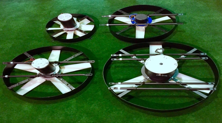
In case anyone is interested…..earlier this year I did a search for diesel electric fans because a friend of mine asked why I was doing Les’s electro-viscous fan instead of going electric. I found this place. They make some huge electric fans for OTR trucks. Even so, they put restrictions on which trucks can run them (under 450hp, ram cooling, etc). It just doesn’t seem to be a feasible proposition for high btu cooling situations.


Sorry for the hijack, but I thought it was kind of interesting when I found it.
 
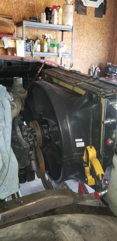
I got back into the garage to finish up the fan shroud. The champion specific radiator mounts came in. That got the radiator centered in the core better. So next it was time to started tackling the upper shroud. I got a set of 3/4" spacers to bring the fan back. Its looks like it going to just clear all the pulleys. But I will know more when I dress the engine fully.
20210515_112501.jpg
20210515_113118.jpg

So I started trimming off a little of the upper shroud at a time to see how well I could make it fit. I must say it turned out better than I expected. It will direct flow through 95% of the radiator. I still have to go in and add some steel to the upper bracket to give me a place to bolt the shroud to. And to fill in the slight gap between the upper bracket and shroud. I ended up cutting off the whole top that wraps over top of the radiator. But thats all the final details I can do later. I just what to make sure I can make it fit and that was successful!
20210515_121852.jpg

I'm even going to add a second set of mounting bolts to make use of these screw holes on the top of the 81-87 shroud.
20210515_121926.jpg

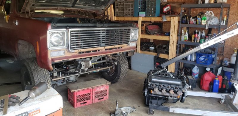
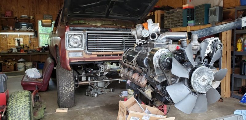
So next I pulled the engine out so I can fully dress it and start to lay out the centermount build.🤘🤘
20210515_141431.jpg
 
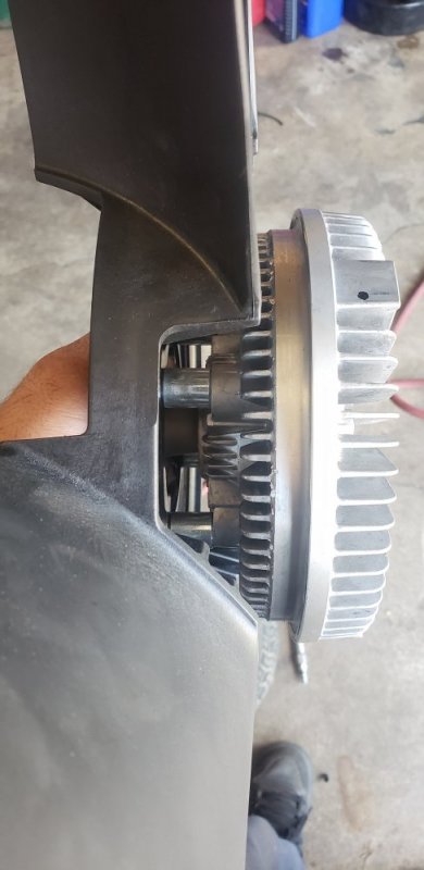
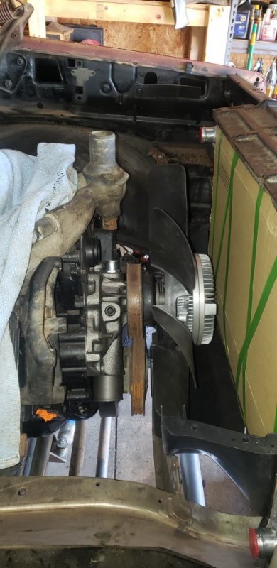
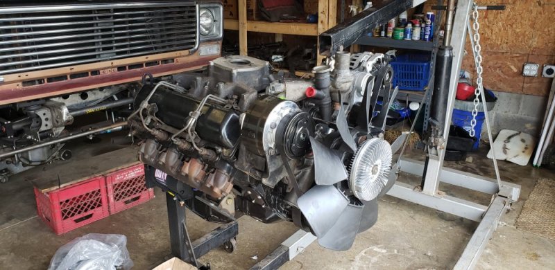
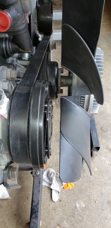
Ive been busy with other stuff around the house all week. Found some time today to dress the engine to prepare for the centermount layout. Looks like I have about 95% of what I need. Got to track down a few small things im missing. But all the important stuff if bolted on. Unfortunately the fan spacers won't work out because the A/C clutch causing an interface issue. So looks like I can either run a smaller fan, or trim the duramax fan diameter down to the standard 19.5" fan. I think im going to trim the fan and balance it because the duramax fan will move more CFM the any standard SBC fan I can get.

20210522_143354.jpg
20210522_143437.jpg
This is the fan back in the standard location without the spacers.

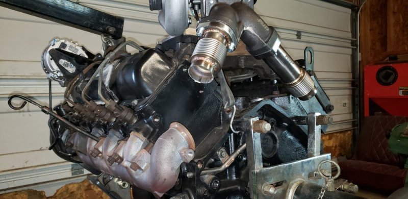
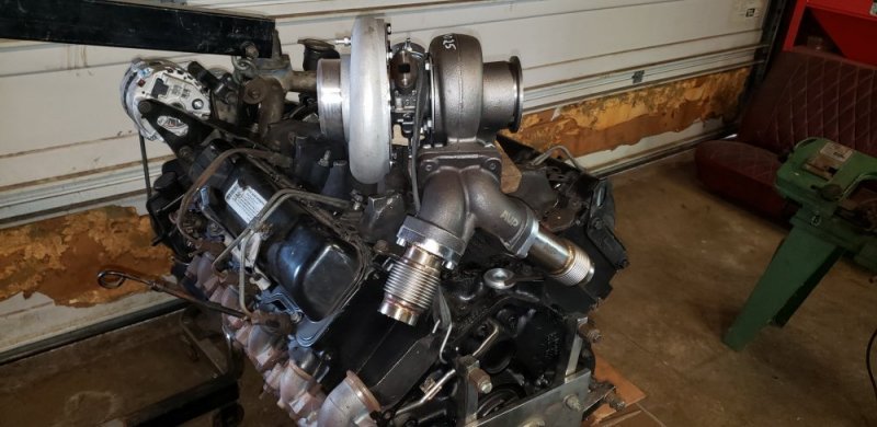
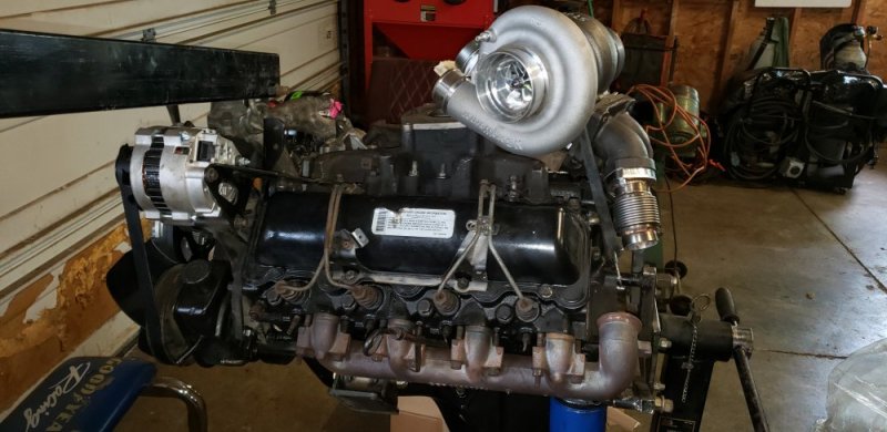
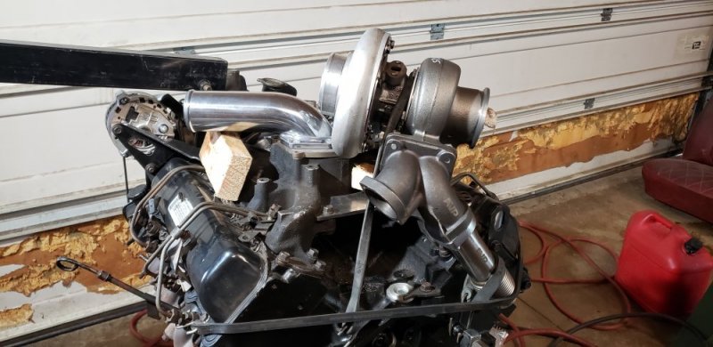
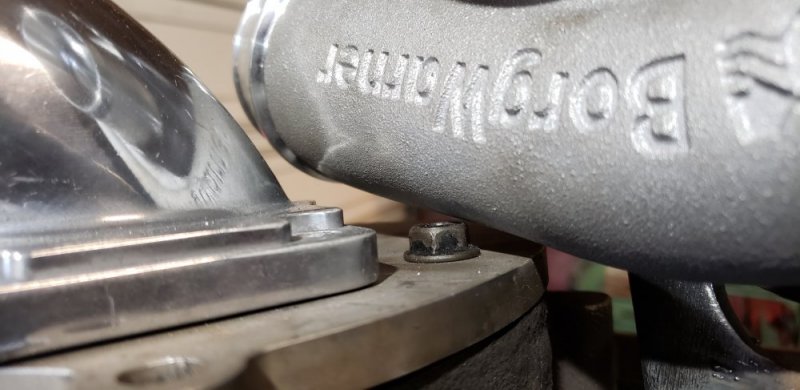
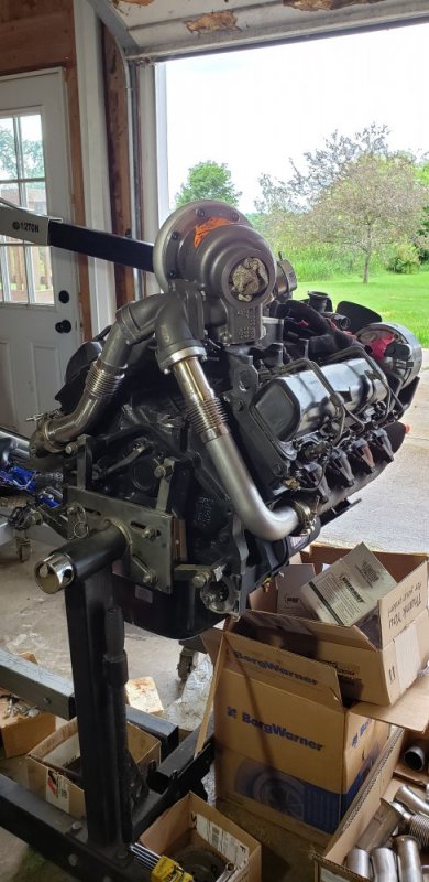
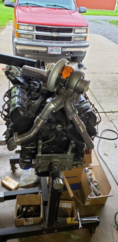
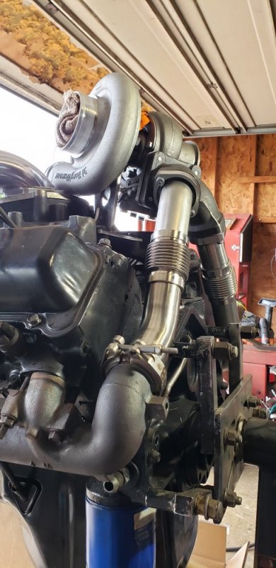
With the engine dressed it was time to started laying out the turbo location. I've seen a few centermount builds done on 6.5s. Everyone of them had the turbo in the same location. I jusy wasn't a fan of how it looked. Plus the crazy amount of heat the collector at the turbo flange is put through I didn't trust the longevity of stainless tube. So this idea came to me like most do, while working on a customers truck. It was a 7.3 and I noticed the T4 style up pipe manifold might just work on a 6.5. So thats the direction I went. I ordered the updated 7.3 up pipe kit. And paired that with a 62/68/.83 T4 gated Borg Warner SX-E. I started to lay out the turbo location and I think its going to work. I trimmed the up pipes down past the bellows so I can fabricate the rest. I still need to play with the turbo placement more to make the drivers up pipe less of a pain in the ass the to make. But I'm happy with how this is coming together. I had also ditch the peninsular upper intake because the turbo wont clear. Looks like im going good have to offset the inlet pipe on the upper. So I will have a new plate cut with no hole so I can figure out where I have room for that.

20210522_152944.jpg
20210522_152927.jpg
20210522_152936.jpg
20210522_152952.jpg20210522_153007.jpg

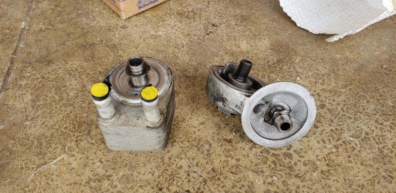
Also im working on a different oil cooler set up. Once again got this idea from a ford van with a 6.8l. Im going to make an adapter to run the water to oil cooler that ford had ran for FOREVER. Its not much smaller than a duramax cooler. And I think it will look a hell of alot better than leaky oil cooler lines running to the front.
20210522_143347.jpg
20210522_180727.jpg
 
The factory spot for the centermount turbo is awkward drain imo. Almost half the drain hole is blocked.
But if thats where you’re going It will work. You can drill it yourself- really don’t need any machining.
I did my optimizer. I didn’t mill out the figure 8 looking oring. I just used blank head gasket material, it seals perfect.
I suppose if you want both oil supply and return exactly like the factory center mount blocks, that indention for the figure 8 oring woul require machining.

If I was to do mine over- I would never used the factory turbo and that oil feed/drain set up.
Use a hose to feed is just as easy and better imo. Those figure 8 orings fail and leak oil, sometimes causing a fire. Turbo hummer/van burns to the ground- 50% chance it’s that oil seal.
Drain, idk best answer. Probably threaded bung welded in the pan.

If ya need pics, measuring, etc. lmk.
 
Problem with water to oil coolers, is that when they do fail they usually take out the engine or whatever else they are used on.
In my case I did not want to compromise my very expensive transmission so I went with almost triple BTU rejection rate mid sized truck air to liquid trans cooler...
The quality of the oil coolers go from CHICOM cheap ass (most common) to expensive aviation and marine units.

I hardly see failures with water to oil coolers. Ford diesels had some issues but the other manufactures didn't seem to have the same problems. Duramax and Cummins both use a water to oil cooler. On the other hand, I replace oil cooler lines weekly on gas GMs. After 18 years of turning wrenches I have never seem the gas style ford cooler leak. So I'm confident if I buy a new one from Ford I wont have any issues.
 
Very slick using the 7.3 hardware! Looks awesome

Is the T4 pedestal also off a 7.3? Or did you custom fabricate connecting the Y pipe to the turbo base? The upgrade kits I quickly looked up have the bellowed pipes and the Y pipe but not the 4 bolt plate/ pedestal for the turbo

Excited to watch this, been curious about a centermount 6.5 for a while now. Thanks for sharing your efforts!

The 94-98 7.3 uses a T4 up pipe manifold. Then they switched to the round style in the 99-03.

Thanks!! I've been waiting for over a year to try and put this together. Hopefully I can fit it under the hood and not have to cut the firewall too much.
 
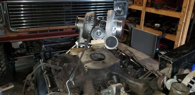
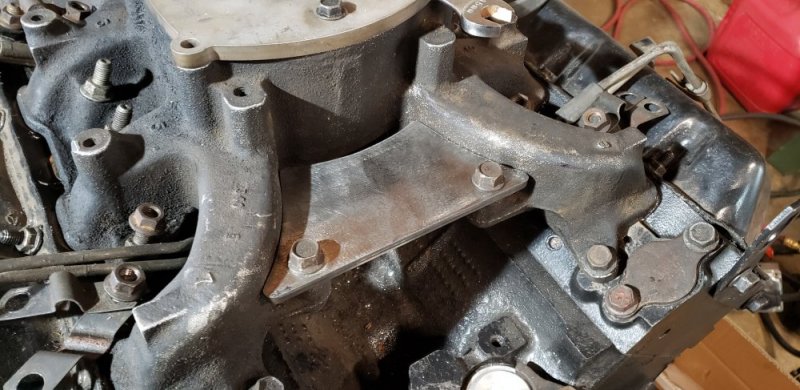
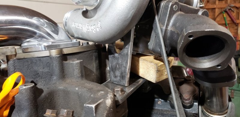
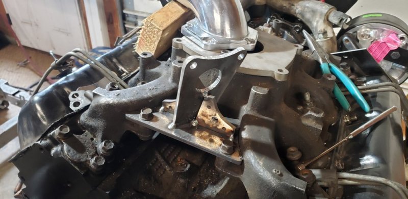
Found some time today to put more work into the centermount build. First project on the list was to build the turbo mount. I needed to determine my final turbo position and solid mount it to the engine some how. After rolling the idea around in my head the past few days I came up with a plan. The mounting tabs on the back of the intake are a perfect place for a mounting plate. This one I cut from 1/4" plate and worked it to fit the back of the intake.
20210529_115955.jpg

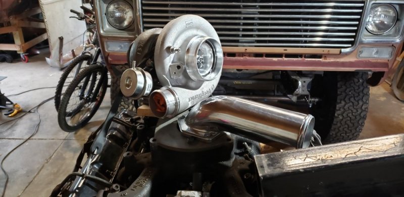
From there I proped the turbo back into position and held it in place with a bungee cord and some blocks of wood. I scored a free 6.4 PS intake elbow from a junk truck at work for free. With a little work I made everything fit and kept it as tight as possible in hopes to clear the stock hood. So looks like more Ford parts are going on this engine. I will have to make a different upper intake plate with a offset hole, but at least I know it will work.
20210529_123957.jpg

20210529_124522.jpg

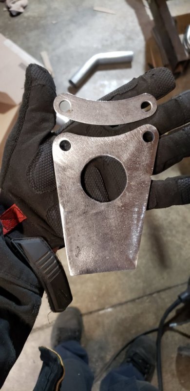
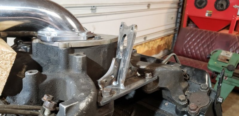
Since I'm attaching the turbo to the intake I didn't want to have the bracket on the turbine housing in fear of heat transfer. So I decided to remove the lower compressor housing clamping bracket and replacing it with my own bracket. Again I made this from 1/4" steel. Took a little while to massage it to match the original bracket at the top. But I'm happy with how it came out.
20210529_142012.jpg

I mounted it to the turbo and tacked it to the lower plate I built. Then I added some support gussets to each side. Good enough for now. Like everything else I will finish weld it once I know I don't have to change it.
20210529_142611.jpg
20210529_161943.jpg
20210529_161925.jpg

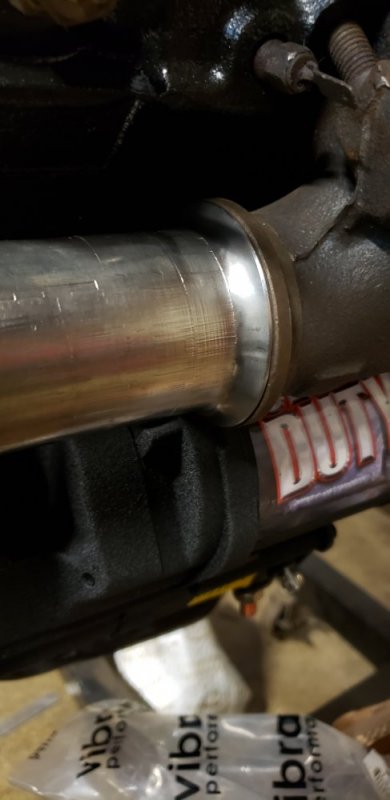
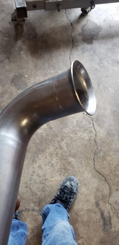
With the mount built I turned my attention to the up pipes. The passenger side was super easy. All I needed was a 90* to make that side work. So I picked up a 2" bend from vibrant with a .065" wall thickness to match the AVP 7.3 up pipes. I cut the 7.3 pipe off past the bellows. And instead ordered a set of vibrant bellows to weld in my self. The two pipes don't line up perfectly, so I figured I could get some wiggle room if the bellow is unwelded when I slide it all together. Unfortunately I won't have those till next week. I did do a test run on the flare connections at the manifolds though. We have the attachment on our exhaust bender at work to do a flared ends. I was just scared it was going to mark the pipe up because how it grips it. But with a little sanding it cleaned up nicely. I should have no issues flaring the ends for the v-band my self. I was starting to think I would have to order weld on ends.
20210528_195544.jpg

The drivers side was a bit more of a challenge. The lower half of the 7.3 up pipes was a good fit. So I cut it off past the first 30* bend. The flare needs to be enlarged to fit the manifold better but thats no big deal. The upper half I had to completely redo the pipe into the flange. With a bit a grinding I was able to slide out the pipe and save the upper flange. Kinda disappointing they are not stainless like the pipes. Almost makes me want to get a set cut from stainless.... that might have to happen 🤔. Since no one makes a 30* bend in the thicker wall thickness. Or really in any wall thickness for that matter I used a 45* again from Vibrant and cut it right past the bend. That allowed me to get the pipe to come out of the flange and line up with the lower half quite nicely. Now I have everything held together with tape and some cardboard. Once the new bellows come in I can flare the pipes and finish this thing up. Coming together nicely 😎 🤘🤘
20210529_183534.jpg
20210529_183543.jpg
It looks off in the picture because the tape / cardboard does a half ass job of holding it together 😄
 
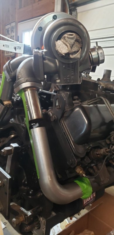
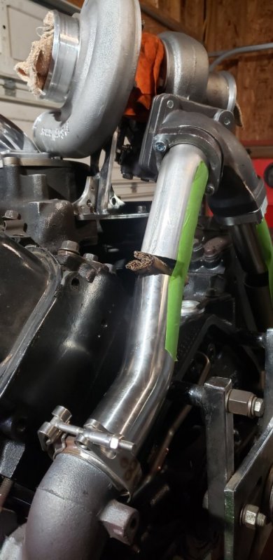
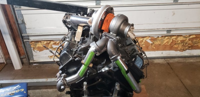
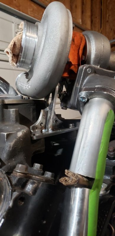
Had to take a few weeks off from the truck for our Alaskan wedding 💒. Then had to play catch up around the house when we got back. Today I got back in the garage to finish the up pipe layout. My vibrant bellows came in while in Alaska so I have everything I needed to finish it up. I flared the ends for my v band clamps at work. Came out really nice, I hardly put a mark on the 90*. The 30* will need some polish work. But I plan on wrapping these so no one will notice anyway.
20210619_123250.jpg

From there I trimmed everything and assembly it. Went together really fast and lines up perfectly!! Its good to see a idea ive had in my head for 2 years finally come together. Im going to leave it unwelded for now so I can make adjustments if needed.
20210619_130118.jpg
20210619_130130.jpg
20210619_130141.jpg
20210619_130300.jpg

About time to stuff this thing back in the truck🤘🤘
 
Back
Top