• Welcome to The Truck Stop! We see you haven't REGISTERED yet.

    Your truck knowledge is missing!
    • Registration is FREE , all we need is your birthday and email. (We don't share ANY data with ANYONE)
    • We have tons of knowledge here for your diesel truck!
    • Post your own topics and reply to existing threads to help others out!
    • NO ADS! The site is fully functional and ad free!
    CLICK HERE TO REGISTER!

    Problems registering? Click here to contact us!

    Already registered, but need a PASSWORD RESET? CLICK HERE TO RESET YOUR PASSWORD!

Making a tube header for the turbo side

n8in8or

I never met a project I didn’t like
Messages
4,290
Reaction score
8,305
Location
Kalamazoo, MI
This is a project I was planning on working on this winter, but since the engine is out right now.....and since I have a #8 piston that's showing excessive heat issues, I decided to tackle it right now. I've been working on this for about 20 hours including making the fixture :eek:, but only 10 of that is actually tube fabrication. My goal for this manifold is for it to be a complete bolt-in in place of the stock manifold. It would be a lot easier to fabricate if I was to relocate the turbo, but I already have a lot of time in my intake and intercooler so I don't want to re-do these. Someday I may do a center mount turbo, but to do it right I will also do a new intake manifold.....so that is a project for another day. I have lots of pics so far so I'll have to do this in multiple posts. I hope you enjoy the diesel porn!

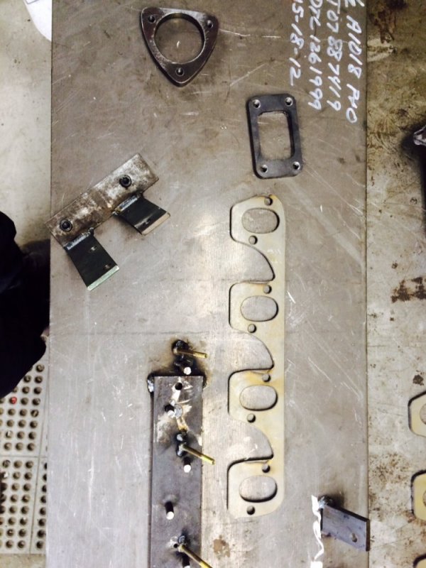
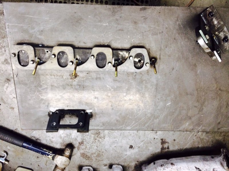
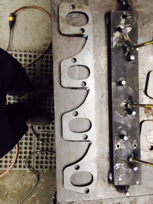
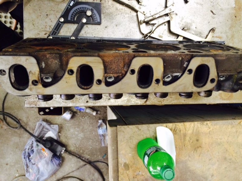
I ordered header flanges from Stan's headers and they showed up just in time. They are really nice quality. It looks like they're laser cut....either that or they're really nice plasma cut. They have reliefs ground in them to clear the bosses on the heads. They're only 1/4" thick, but they said they don't worry about making them out of 3/8" because the bolts are close to the ports....I'm not sure about that, but we'll see how well they hold up.

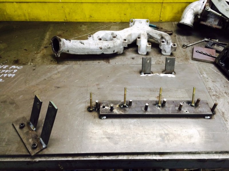
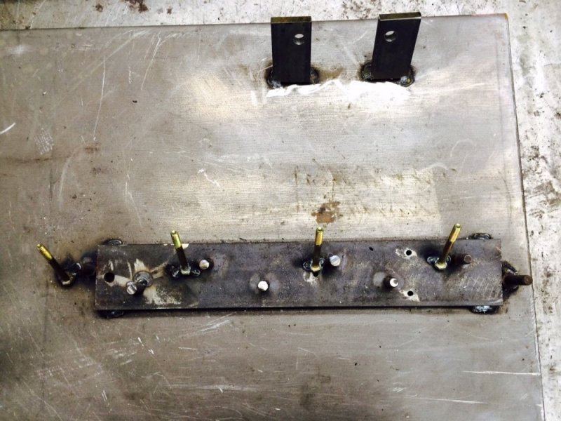
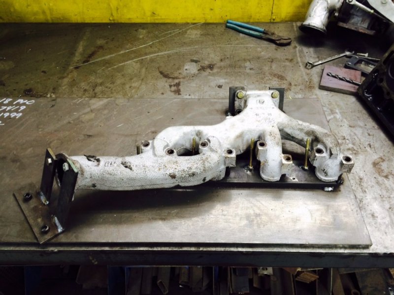
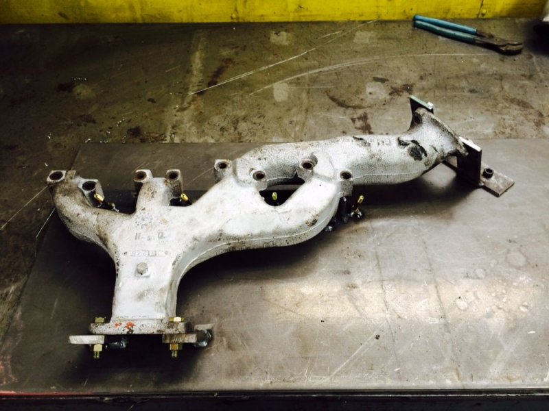
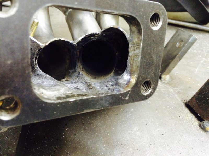
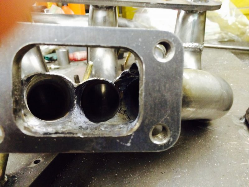
I was lucky enough to get a nice big chunk of 1/2" plate from work to make a fixture out of. I used the stock manifold to key off of as you can see in the pics. I got a T3 turbo flange from Summit Racing and made the 3 hole flange for the crossover out of 1/2" plate. The gold zinc plated screws on the fixture represent where the glow plugs are so I didn't block those and make them unserviceable.
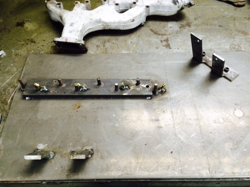
Fixture 1.jpg Fixture 2.jpg Fixture 3.jpg Fixture with flanges 1.jpg Fixture with flanges 2.jpg Fixture with manifold 1.jpg Fixture with manifold 2.jpg Header flange 1.jpg Header flange 2.jpg
 
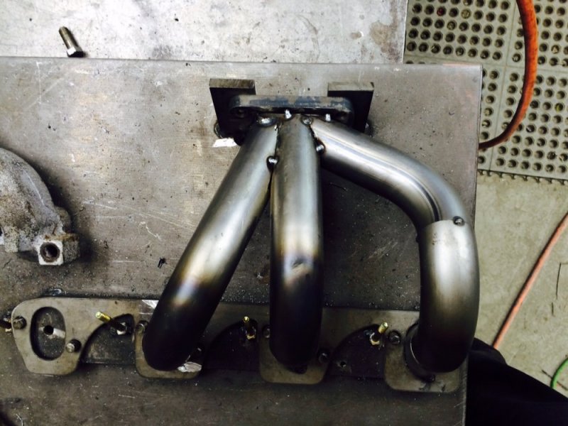
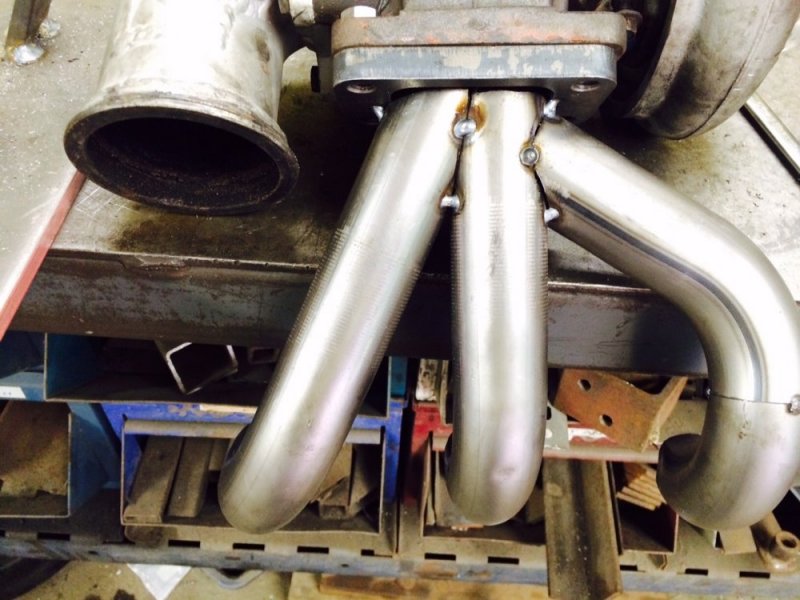
I decided to start with the easy tubes, which in hindsight may not have been the best decision, but it has turned out ok so far. I ended up going through 3 iterations of the 2,4&6 tubes before landing on something that looked like it would work right.

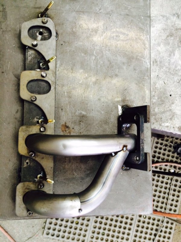
Here is the first attempt. I went for a straight shot and had them dump into the bottom side (or back side depending on how you look at it) of the turbo flange. I was very pleased with how well these turned out except they didn't fill the ports of the header flanges all that well, though that was a minor and easily fixed detail.

2and4 1.jpg 24and6 1.jpg
 
I then realized that I had planned on the exhaust from the crossover dumping into the backside of the turbo flange so I decided to start modifying to accommodate that. This was just a rough adjustment that would have been polished later....not that it matters now.

24and6 1.2 1.jpg 24and6 1.2 2.jpg 24and6 1.2 3.jpg 24and6 1.2 4.jpg
 
As I started looking at everything more and more, I realized that I had more room I could use on the outside of this, but I was going to be very restricted on the back side due to injector lines and stuff. So I decided to use the same basic tubes but space them out further so I'd have more room to work with on the back side. Luckily there is a 6.5 turbo in a truck at the junkyard 5 minutes from me, so I took so measurements to confirm how much space I had. This ended up being the right decision. Also with the new angle of the tubes they fill out the ports of the flanges much better. This turned out exactly how I wanted (and needed).

24and6 2.0 1.jpg 24and6 2.0 2.jpg 24and6 2.0 3.jpg 24and6 2.jpg
 
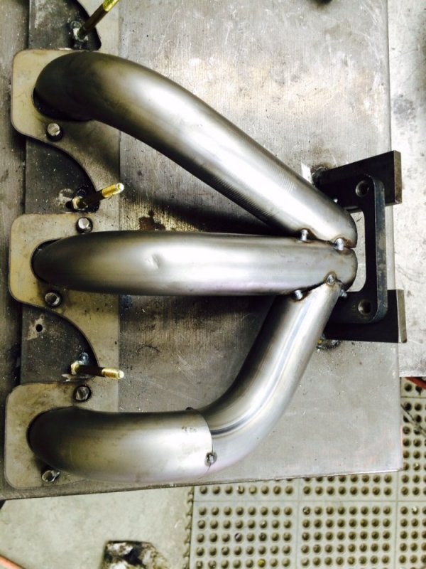
Things had been progressing pretty well at this point, and relatively simply, but now it was time to do the #8 tube. It actually took me 2 attempts to do this. The first attempt I ran the tube behind the other 3 tubes. This worked well, but it wasn't going to leave me much real estate for the exhaust from the crossover. Here is what the first attempt looked like.

246and8 1.0 1.jpg 246and8 1.0 2.jpg 246and8 1.0 3.jpg
 
I decided it made more sense for the real estate on the backside to be used for the crossover so I cut the tube off and went a new direction. I realized that I had some real estate down low available, plus plenty of room between the #2 and #4 tubes so I decided to run #8 there instead. It was a good decision. As you can see I saved part of the old #8 tube. That will come into play later.

As you can see, I put the old block and head to good use as a mockup fixture for this project. Good thing I hadn't scrapped them yet! I may hang on to them in fact just for this reason.

There is sure a lot going on here even without the crossover exhaust! And then making sure the downpipe won't hit it as well is a further complication. I quickly realized why other people aren't doing this. But I was determined to make it work.

246and8 2.0 1.jpg 246and8 2.0 2.jpg 246and8 2.0 3.jpg 246and8 2.0 4.jpg 246and8 2.0 5.jpg 246and8 2.0 6.jpg
 
And finally here is where I left off tonight. I have a complete mockup of the header done! :D:woot::shame::p

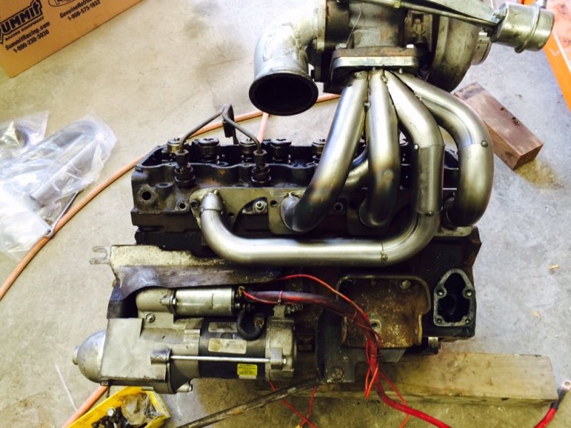
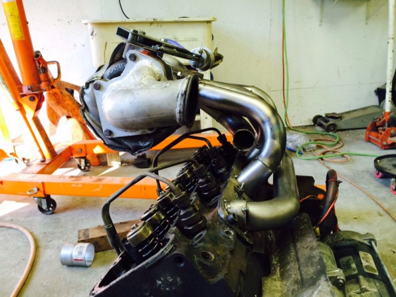
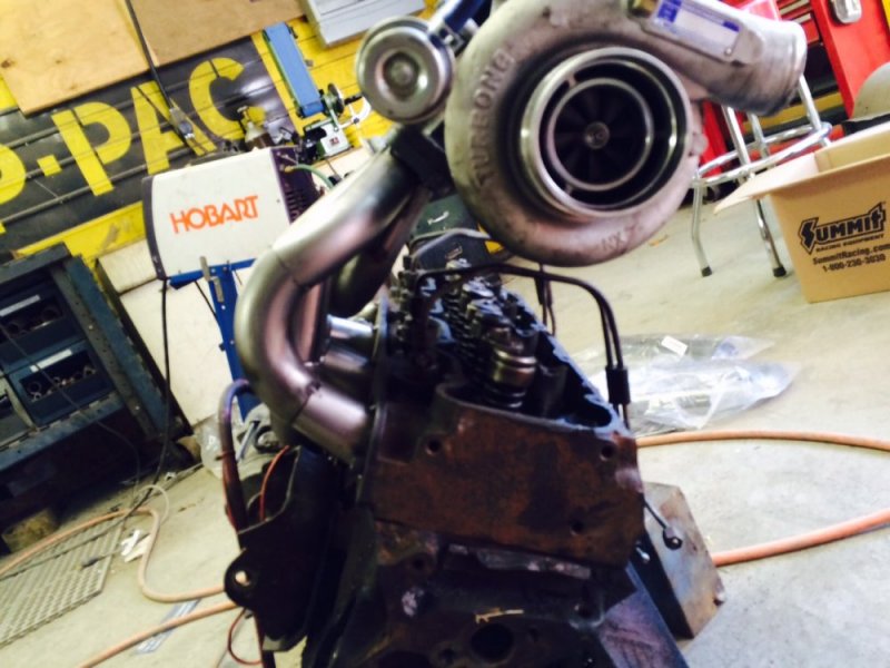
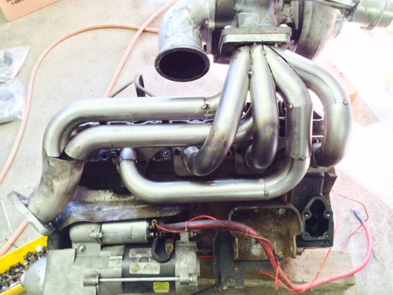
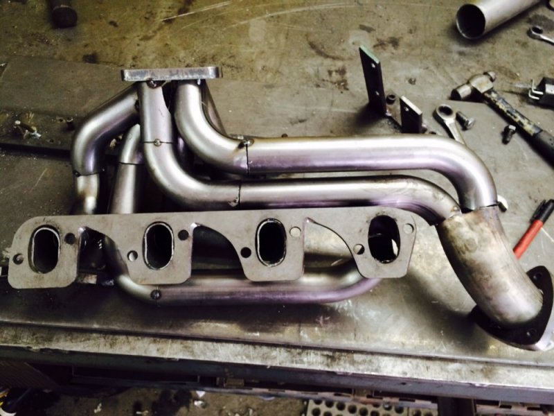
As you can see, I did something a little unconventional with the crossover tubing. My initial plan had been to run 2.5" tube all the way to the turbo flange, but there just wasn't enough room when all was said and done. So since I had plenty of the 1-5/8" tubing I decided to split the exhaust so I could package it better. It's almost the same cross sectional area, so I don't figure I'm losing much by doing it this way. Even if I am, it's WAY better than the OEM design, so who cares in the grand scheme of things?

Tomorrow I will be taking the header apart to weld each individual tube and then pray that it all goes back together the same way :nailbiting:. With the weld fixture it should be fine. And then there are a couple small patches that I need to make as well to finish all of the connections. If all goes well it should be done tomorrow, but we'll see. If I have time left I may do the driver's side manifold too, but that one isn't near the problem (in my estimation) as the passenger side one is (what was GM thinking running the crossover exhaust over the #6 and 8 ports!!??).

Mockup 1.jpg Mockup 2.jpg Mockup 3.jpg Mockup 4.jpg Mockup 5.jpg Mockup 6.jpg Mockup 7.jpg
 
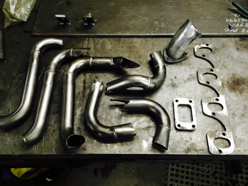
Oh I forgot to mention: for tubing I am using 1-5/8" 16 gauge tubing from Summit Racing. I bought some U and J bends and cut them to the size and shape that I need. I sure wish I had a TIG welder at home, but I'll just have to do the best I can with my MIG. It will be "OK", just not as awesome as it could be.
 
I've thought about this before but was just going to use a collector larger than the original manifold. You wouldn't need all the tubing then, also IIRC headers are built with the same length tube for each cylinder to equalize back pressure. Looks interesting though, looking forward to the results.
 
Very Cool! I like how you separated the crossover from the left banks of cylinders. I wonder how it will sound?

Thanks. I wouldn't expect the sound to change that much but I guess it's possible. We'll see.
I've thought about this before but was just going to use a collector larger than the original manifold. You wouldn't need all the tubing then, also IIRC headers are built with the same length tube for each cylinder to equalize back pressure. Looks interesting though, looking forward to the results.
Oh yes, in their truest form headers should be equal length to equalize the pulses to the turbine, but that wasn't my main goal. Since the overall design is so imbalanced due to the long crossover from the driver side I'm not too worried about the individual cylinders being imbalanced. I think I see what you're saying about the larger collector. I was thinking about a large log style manifold after seeing all the work this thing was, but I've also enjoyed the challenge of building this out of tube. I hope the results are worth the effort.....and yet this has been a fun way to spend some time off from work as well so even if I don't notice huge improvements I don't think I'll regret it....unlike the camshaft :rolleyes:
 
My understanding of headers is equal length is for higher rpm and tri y is better for torque at least in gassers
 
My understanding of headers is equal length is for higher rpm and tri y is better for torque at least in gassers

This is true for the most part, but I think it mainly applies to a naturally aspirated engine because it uses the exhaust from the one cylinders to scavenge another cylinder. The tubing configuration optimizes that effect at different rpm in conjunction with tubing size and length. I know (or THINK I know ha) less about turbo headers/manifolds. I have no delusions about making the perfect system, I just want to make something better than the factory manifold.....and have a little fun while doing it.

How the heck do you get to all the welds on the flange?

My plan is to take it back apart and weld it in stages. It's still going to be a bit of a trick though.
 
Have to enjoy some fab work just for trying it. Funny, I was thinking "how he's got a tig" right before reading not so. Just be patient and you'll get it.
 
Meant to say hope, not how. Looking cool. #8 looks a bit long, but like you say no scavange effect so I wonder how much difference its really going to make. Im sure it's all going to do way better than stock manifold. And while the 1 bigger pipe out might flow a tiny bit more, i think it looks cooler with the twins coming out.

Cant wait to see finished piece. Doing the other side also,right?
Indeed, in a perfect world all 4 would be the same length but I just couldn't see a reasonable way to do that with the packaging constraints. Way better than the stock manifold overall though I think, so that's my main concern.

Yes I would like to do the other side too, we'll see how time works out. I will probably at least make the fixture off the manifold while it's out and then I can make it later at my leisure.
 
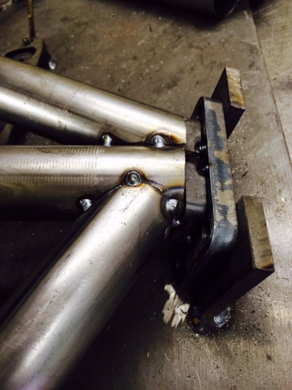
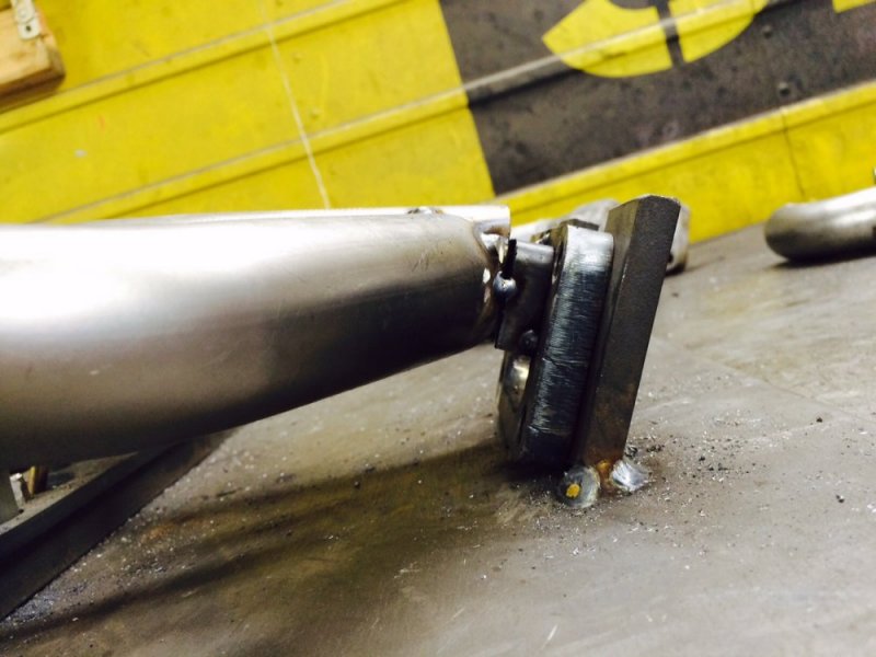
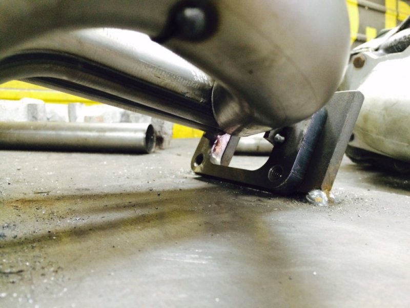
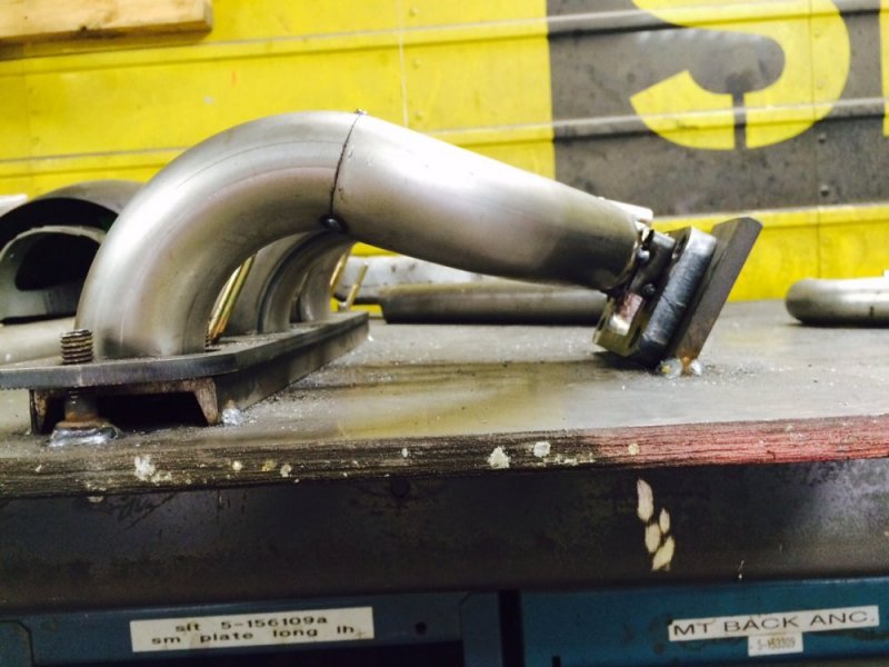
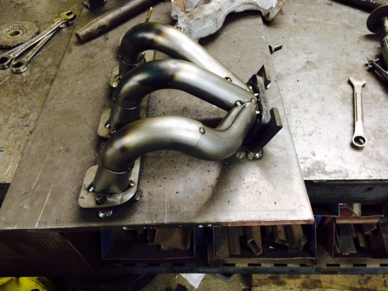
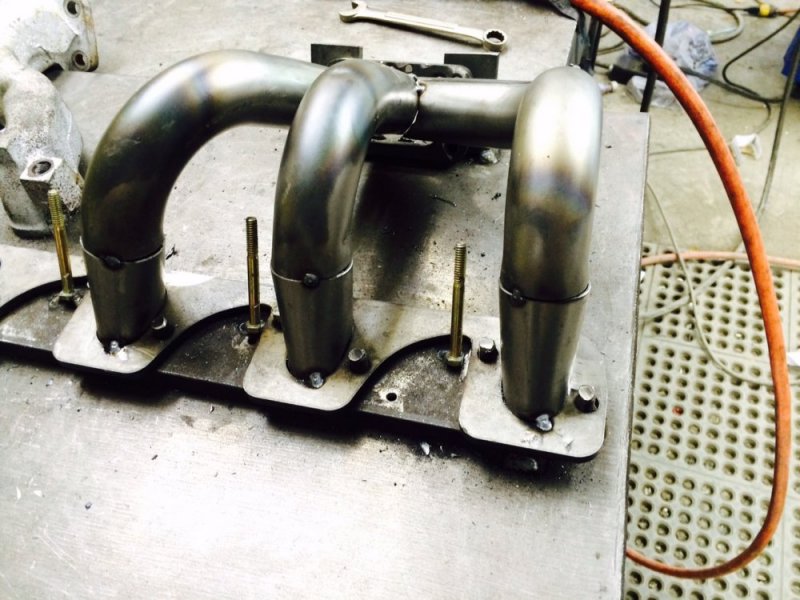
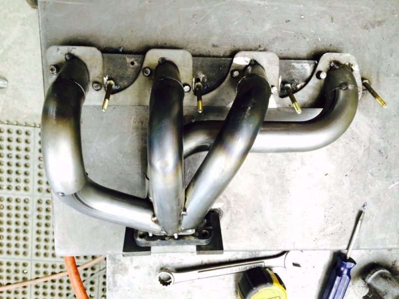
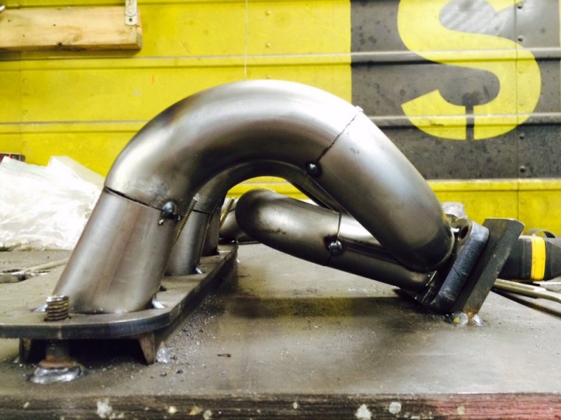
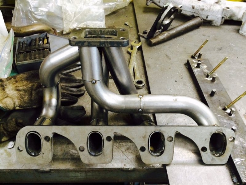
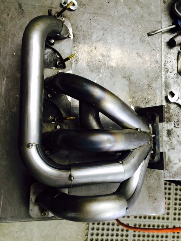
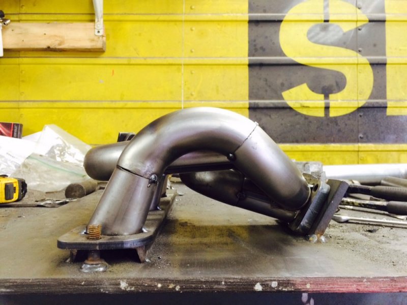
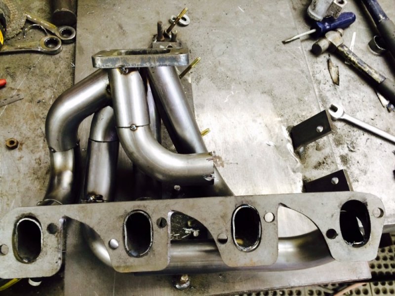
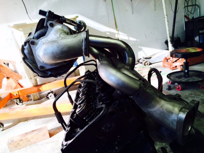
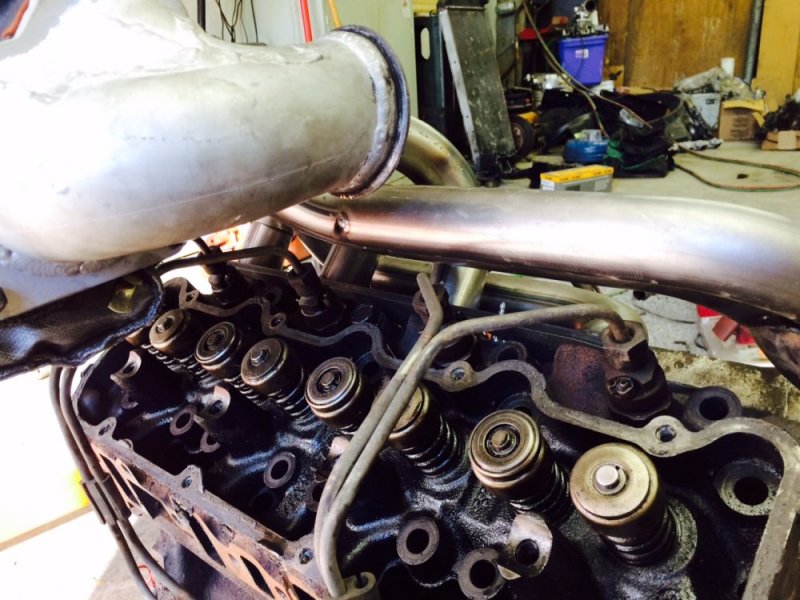
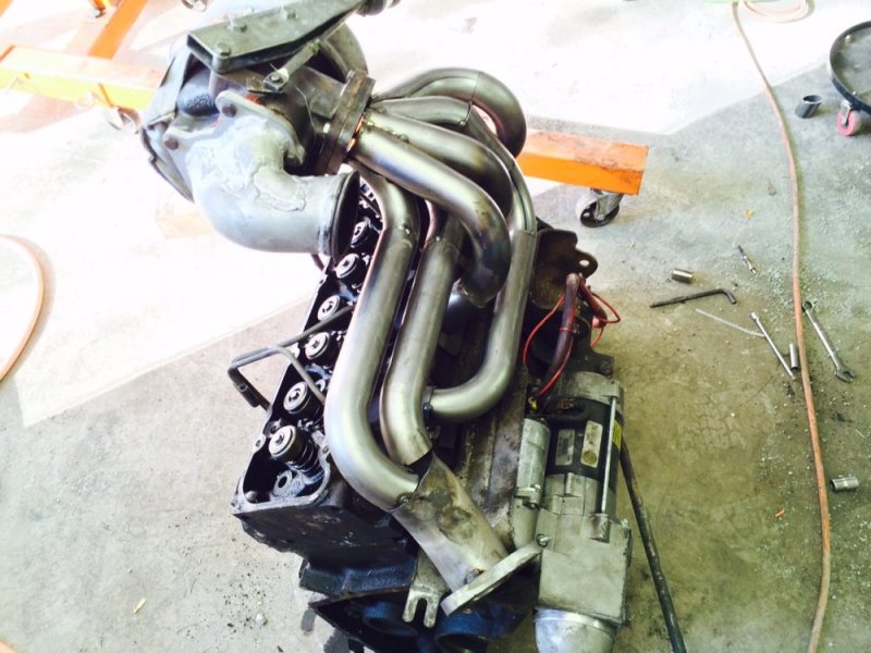
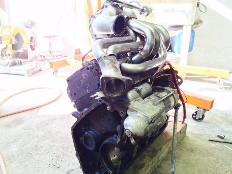
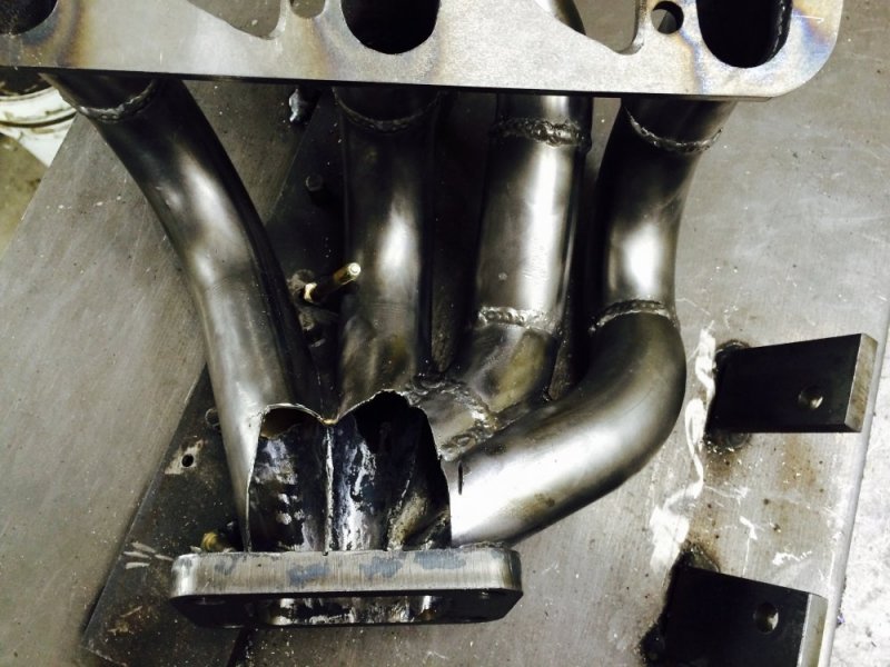
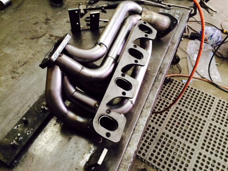
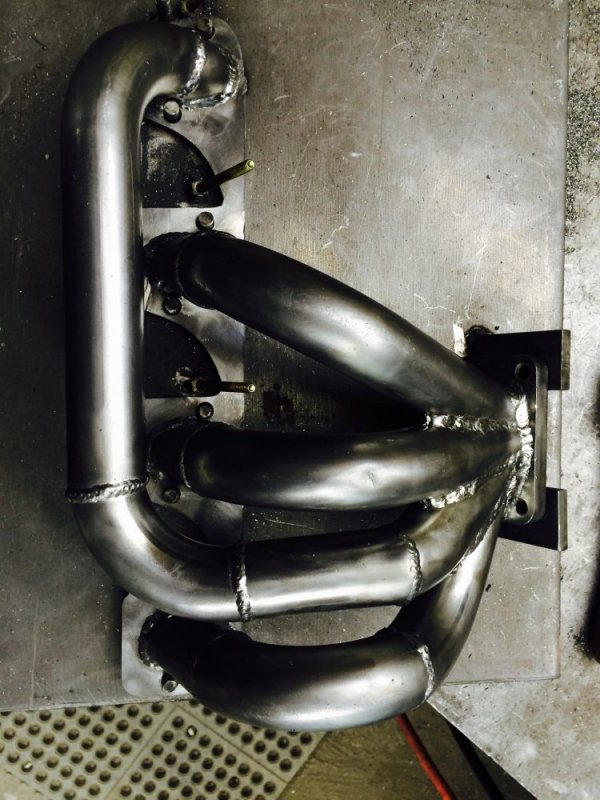
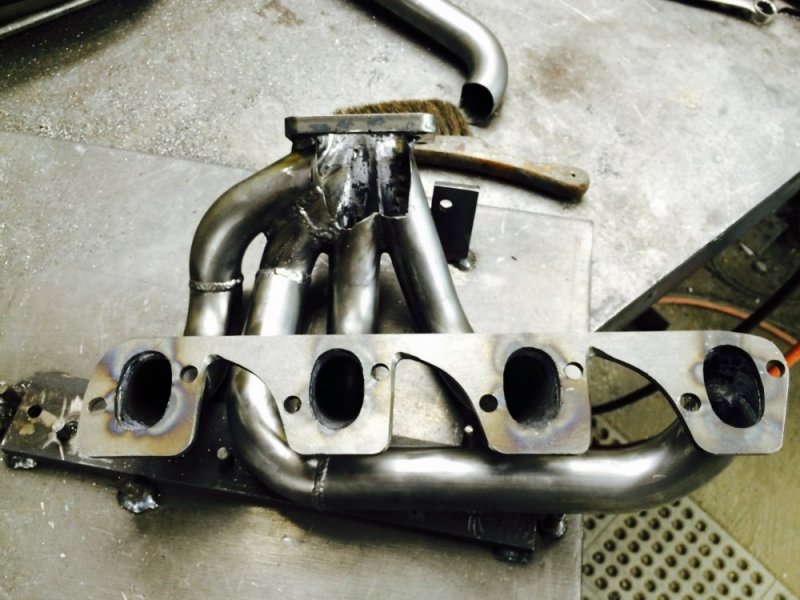
The 4 main tubes are done. I think it's turning out well. You can hide a lot of ugly cuts with some mig welds and grinding :rolleyes:. I need to run out now and get supplies for the mounting bolt standoffs because I think I need to get those done before I put the other pipes in the way. More later.

image.jpg image.jpg image.jpg image.jpg image.jpg
 
Back
Top