Twisted Steel Performance
Anything worth doing is worth overdoing.
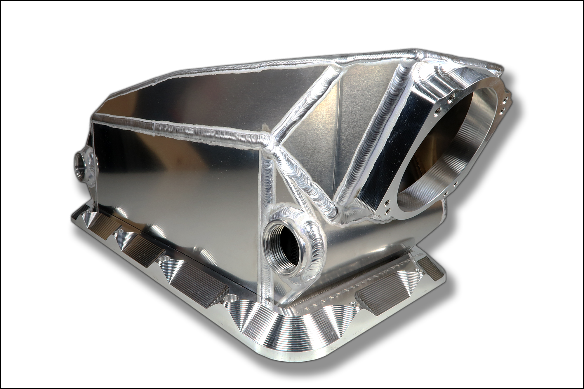
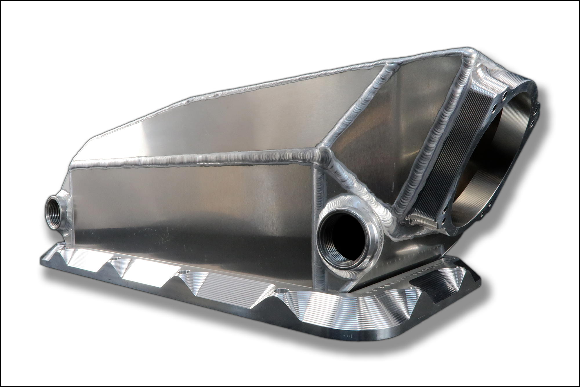
Here are a few pics of my latest project, a custom intake, it's a work in progress, cad drawing, cutting, testing, changing, more cutting and testing..
The flanges & runners are as they will be, laser cut 6061T6 Aluminum, flanges are 3/8", runners are 1/8"...
More to come...


.JPG")
.JPG")
.JPG")
The flanges & runners are as they will be, laser cut 6061T6 Aluminum, flanges are 3/8", runners are 1/8"...
More to come...