Navigation
Install the app
How to install the app on iOS
Follow along with the video below to see how to install our site as a web app on your home screen.
Note: This feature may not be available in some browsers.
More options
-
Welcome to The Truck Stop! We see you haven't REGISTERED yet.
Your truck knowledge is missing!
- Registration is FREE , all we need is your birthday and email. (We don't share ANY data with ANYONE)
- We have tons of knowledge here for your diesel truck!
- Post your own topics and reply to existing threads to help others out!
- NO ADS! The site is fully functional and ad free!
Problems registering? Click here to contact us!
Already registered, but need a PASSWORD RESET? CLICK HERE TO RESET YOUR PASSWORD!
You are using an out of date browser. It may not display this or other websites correctly.
You should upgrade or use an alternative browser.
You should upgrade or use an alternative browser.
Emmott's Initiation
- Thread starter emmott
- Start date
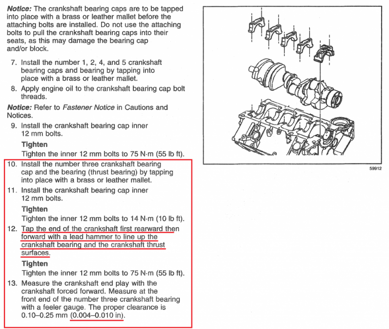
Retoactive update.. last month when I got my block back and started plastigauging, everything I checked was within spec. Main bearings were all 0.0025" on the green, so I lubed up the main mearings and installed the crankshaft but noticed binding on cap #3. I followed the GM manual with exception of the outer studs, which I had inserted without nuts at the same time that I inserted the inner 12mm studs with nuts. When the #3 was in place and the 12mm studs torqued to 10 ft-lbs the crank would bind on the front upper / rear lower thrust bearings and I could not fit a 0.004 feeler gauge, even after tamping the crank to align the thrust bearing surfaces. I removed the 10mm studs and reseated the cap, then the crank was no longer binding but the 10mm studs would not thread in.
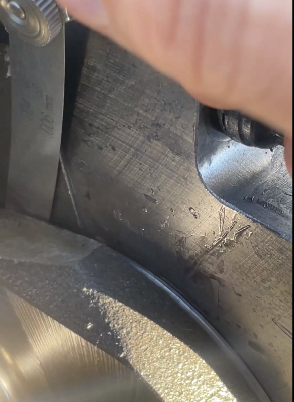
I pulled the cap and looked closely at the alignment of the new splayed main holes and discovered they were out of alignment, enough that the 10mm studs were pushing the cap alignment out of spec for thrust bearing clearances.
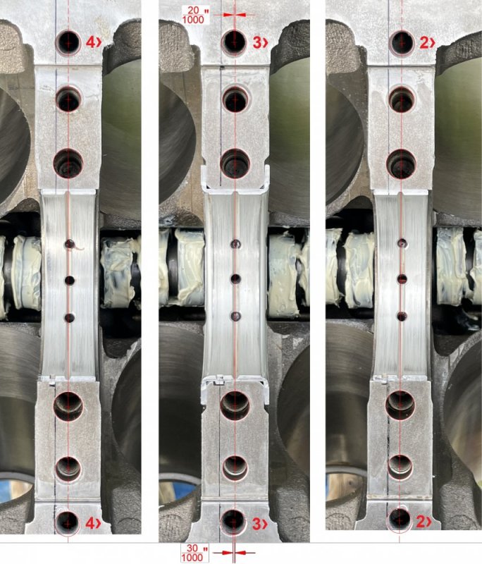
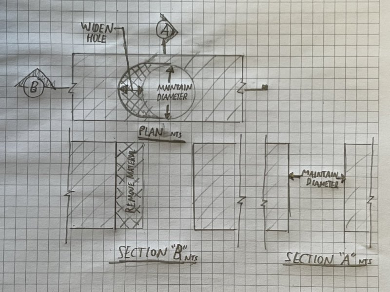
I took an airphoto of the webs, skeched up lines and approximate dimensions in CAD, and sent the above picture to the machinist who originally did the work. They indicated the drilling and tapping was outsourced to a subcontractor who were not engine specialists, and they must not have understood the importance of hole alignment forward/backward on an engine block. They took the block back with the main bearings, caps, and crankshaft, and returned them to me the same day with the issue fixed and the crank re-polished free of charge. They fixed the #3 alignment issue by offset reaming the outer holes on the #3 cap, similarly to the below sketch.
Once I got back home, I installed the crankshaft again and aligned the thrust bearing caps, the upper and lower thrust surfaces aligned perfectly. With the crank forced forward, the 0.004" feeler gauge would fit but the 0.010" would not, on both the upper and lower thrust surfaces. Same withe the rear upper and lower thrust bearing surfaces with the crank forced backward. I removed the caps, cleaned the 10 mm splayed holes with an ARP thread chaser, swabbed with q-tips, and applied Permatex Maximum Temperature Thread Sealant to the M10 studs and bolt holes (since they penetrate into thewater jacket) , then re-seated the caps again.
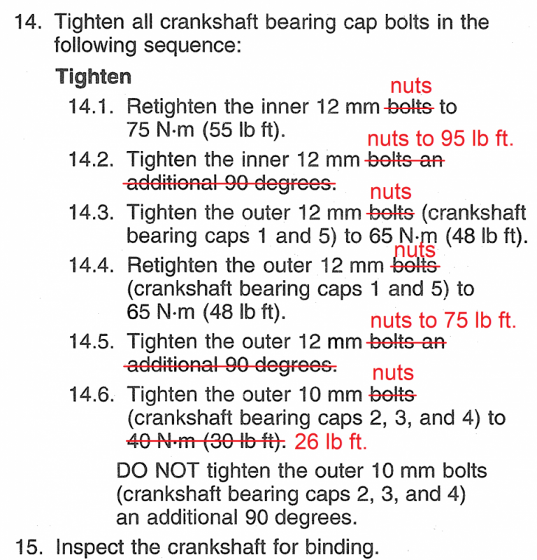
With the crankshaft caps and studs installed, I torqued the nuts in the following torque sequence for ARP studs on splayed mains:
I re-checked the crank for binding and the thrust clearances, was easily turnable with one hand on the nose.
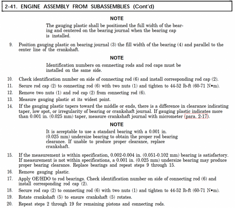
I then went on to installing the pistons and connecting rods. The new pins and small ends of the rods were measured by the machinist to be within spec, same with the big ends - they measured and told me that my standard size upper and lower bearings would work just fine. I plastigauged the rod bearings and like the main bearings were all close to 0.0025" on the green. Side clearances checked out as well with the feeler gauge.
Piston rings were measured and gapped by a machinst, but I re-checked in the cylinder with a feeler gauge before installing on the pistons. I used mahle bearing guard on the bearings, lithium on the cam, pins, and gears, and 2-stroke oil on the pistons. I ensured the dot stamped on the top ring was facing up and the gapless #2 ring was on the bottom.
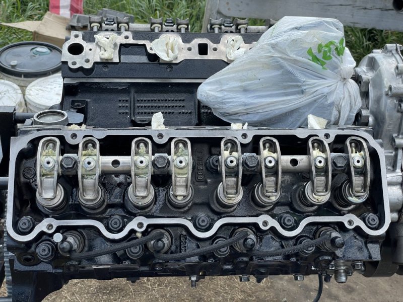
![IMG_0002[1].JPG IMG_0002[1].JPG](https://www.thetruckstop.us/forum/data/attachments/54/54112-521d43d29093bcd8b4fd538173ba99c0.jpg)
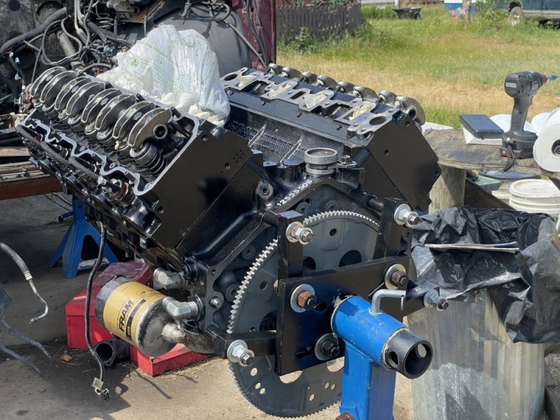
![IMG_0004[1].JPG IMG_0004[1].JPG](https://www.thetruckstop.us/forum/data/attachments/54/54113-c52a359a66a57c5b65d00fe103aa2f12.jpg)
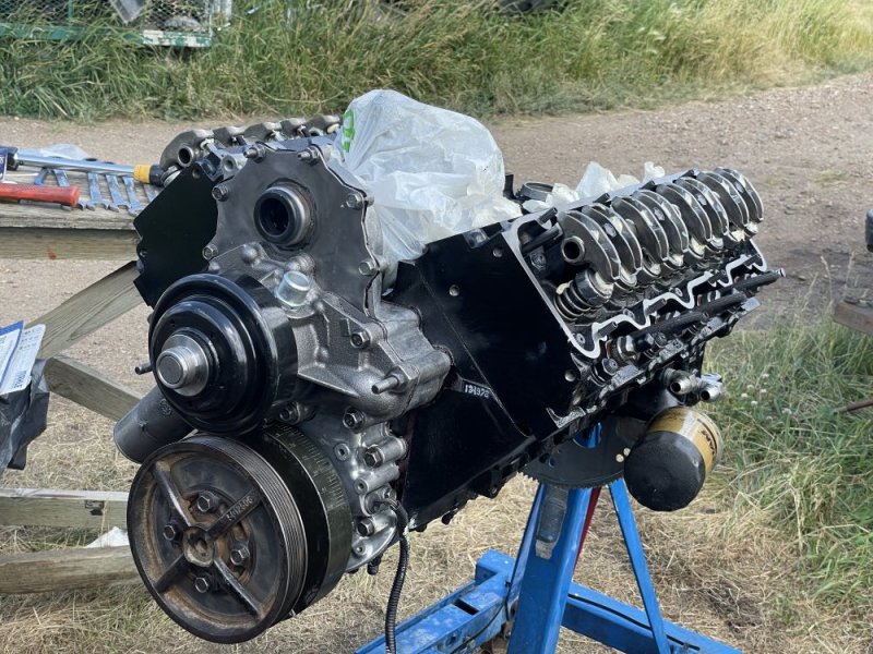
Timing gear installed (lubed with white lithium grease after photo).
![IMG_0048[1].JPG IMG_0048[1].JPG](https://www.thetruckstop.us/forum/data/attachments/54/54114-78e6cf2786f0c1c627b02b25ff84fa2a.jpg)
I picked up new old stock 5234530 valve lifters. Submurged in diesel overnight, primed in the morning, submurged in lucas, then installed. I coated the lifter guides and retainers in lithium grease and installed.
![IMG_E0079[1].JPG IMG_E0079[1].JPG](https://www.thetruckstop.us/forum/data/attachments/54/54115-cdb6243b907b7b6bf7abf8714a512909.jpg)
I also installed the timing cover, 251603 water pump, and DS4-5288 injection pump, using mahle gaskets and thinly brushed Parmatex Hi-Tack gasket sealant onto all contacting surfaces. Thankfully I marked my old IP and timing cover with a cold chisel prior to teardown, so I just re-aligned the marks. Time shet should go smoothly, but I have OTC-6087 wrenches, J-29872 and an Auto-Enginuity scanner just in case.
Tomorrow if I have time I will clean the mating surfaces and install the heads and studs. I already chased and swabbed the block threads and will use Permatex Maxumim Temperature thread sealant on the coarse stud threads.

I pulled the cap and looked closely at the alignment of the new splayed main holes and discovered they were out of alignment, enough that the 10mm studs were pushing the cap alignment out of spec for thrust bearing clearances.

I took an airphoto of the webs, skeched up lines and approximate dimensions in CAD, and sent the above picture to the machinist who originally did the work. They indicated the drilling and tapping was outsourced to a subcontractor who were not engine specialists, and they must not have understood the importance of hole alignment forward/backward on an engine block. They took the block back with the main bearings, caps, and crankshaft, and returned them to me the same day with the issue fixed and the crank re-polished free of charge. They fixed the #3 alignment issue by offset reaming the outer holes on the #3 cap, similarly to the below sketch.

Once I got back home, I installed the crankshaft again and aligned the thrust bearing caps, the upper and lower thrust surfaces aligned perfectly. With the crank forced forward, the 0.004" feeler gauge would fit but the 0.010" would not, on both the upper and lower thrust surfaces. Same withe the rear upper and lower thrust bearing surfaces with the crank forced backward. I removed the caps, cleaned the 10 mm splayed holes with an ARP thread chaser, swabbed with q-tips, and applied Permatex Maximum Temperature Thread Sealant to the M10 studs and bolt holes (since they penetrate into thewater jacket) , then re-seated the caps again.

With the crankshaft caps and studs installed, I torqued the nuts in the following torque sequence for ARP studs on splayed mains:

I re-checked the crank for binding and the thrust clearances, was easily turnable with one hand on the nose.
I then went on to installing the pistons and connecting rods. The new pins and small ends of the rods were measured by the machinist to be within spec, same with the big ends - they measured and told me that my standard size upper and lower bearings would work just fine. I plastigauged the rod bearings and like the main bearings were all close to 0.0025" on the green. Side clearances checked out as well with the feeler gauge.

Piston rings were measured and gapped by a machinst, but I re-checked in the cylinder with a feeler gauge before installing on the pistons. I used mahle bearing guard on the bearings, lithium on the cam, pins, and gears, and 2-stroke oil on the pistons. I ensured the dot stamped on the top ring was facing up and the gapless #2 ring was on the bottom.
![IMG_0002[1].JPG IMG_0002[1].JPG](https://www.thetruckstop.us/forum/data/attachments/54/54112-521d43d29093bcd8b4fd538173ba99c0.jpg)
![IMG_0004[1].JPG IMG_0004[1].JPG](https://www.thetruckstop.us/forum/data/attachments/54/54113-c52a359a66a57c5b65d00fe103aa2f12.jpg)
Timing gear installed (lubed with white lithium grease after photo).
![IMG_0048[1].JPG IMG_0048[1].JPG](https://www.thetruckstop.us/forum/data/attachments/54/54114-78e6cf2786f0c1c627b02b25ff84fa2a.jpg)
I picked up new old stock 5234530 valve lifters. Submurged in diesel overnight, primed in the morning, submurged in lucas, then installed. I coated the lifter guides and retainers in lithium grease and installed.
![IMG_E0079[1].JPG IMG_E0079[1].JPG](https://www.thetruckstop.us/forum/data/attachments/54/54115-cdb6243b907b7b6bf7abf8714a512909.jpg)
I also installed the timing cover, 251603 water pump, and DS4-5288 injection pump, using mahle gaskets and thinly brushed Parmatex Hi-Tack gasket sealant onto all contacting surfaces. Thankfully I marked my old IP and timing cover with a cold chisel prior to teardown, so I just re-aligned the marks. Time shet should go smoothly, but I have OTC-6087 wrenches, J-29872 and an Auto-Enginuity scanner just in case.
Tomorrow if I have time I will clean the mating surfaces and install the heads and studs. I already chased and swabbed the block threads and will use Permatex Maxumim Temperature thread sealant on the coarse stud threads.
Last edited:
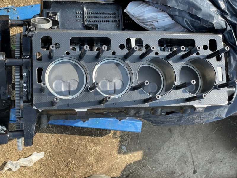
Today I checked the block and heads with a machinists straight edge, cleaned the block and head surfaces, and cleaned the injector thrust washer mating surfaces. I also installed the right head and injectors.
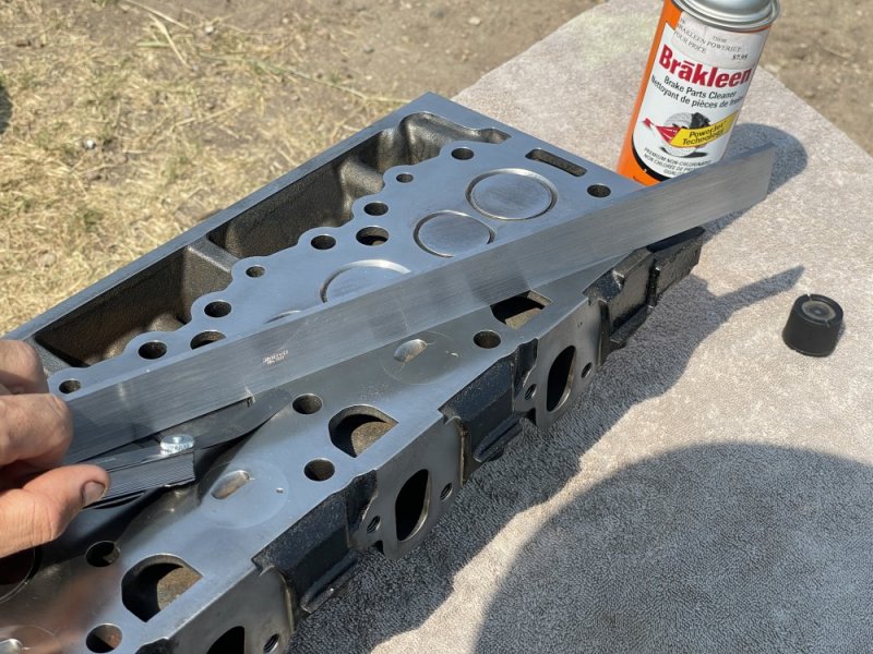
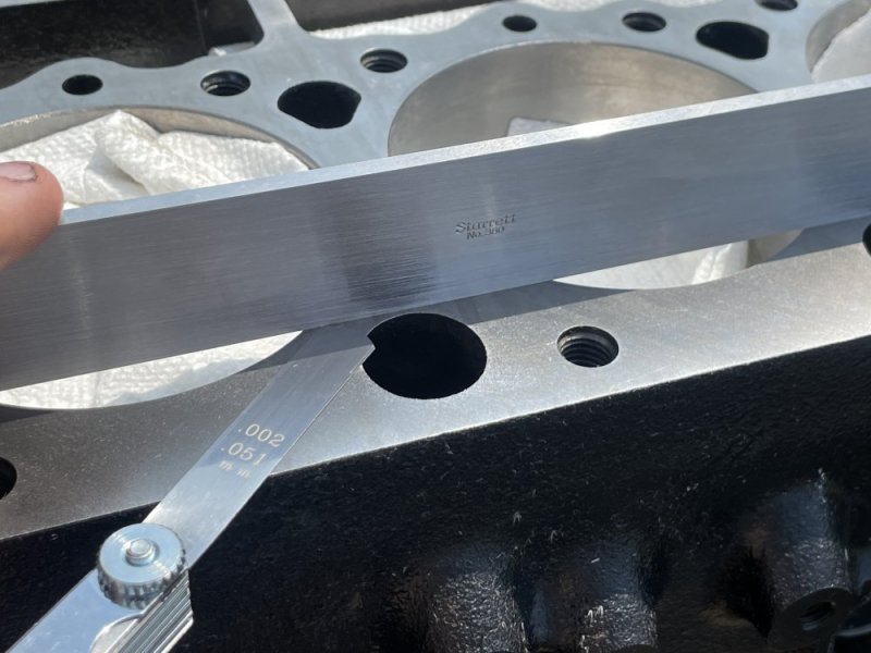
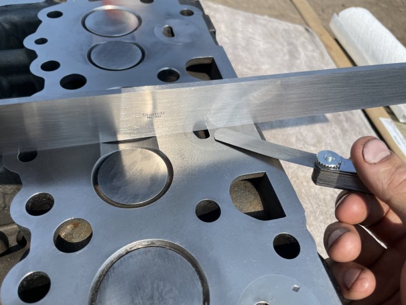
Once the surfaces were confirmed to be within spec, I swabbed the block threads with a Q-tip and Permatex Maximum Temperature thread sealant. I previously chased the threads with ARP chasers and swabbed them clean earlier in the week. I coated the coarse threads of the studs with sealant as well and screwed them in hand tight, wiped away the excess from the block surface, then again ensured the rest of the block surface was clean.
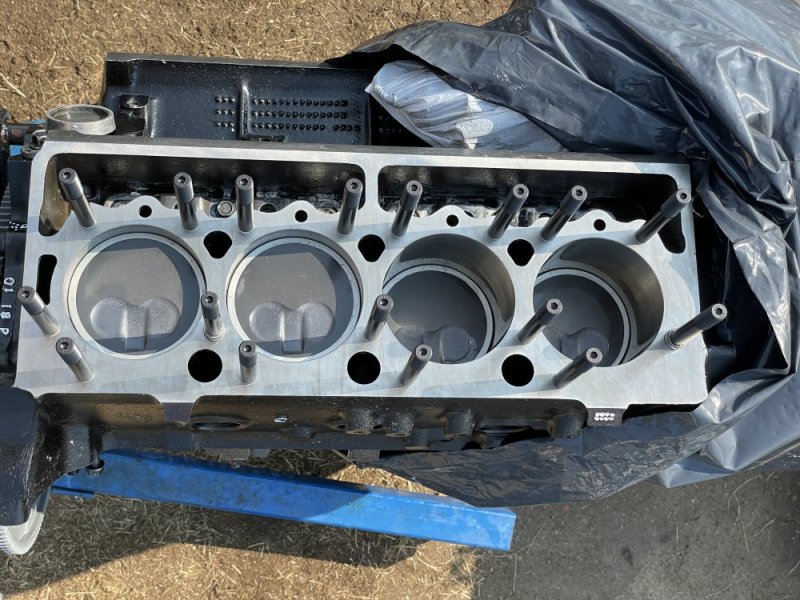
Since my heads were decked once before, I installed a 0.010" thicker gasket. Mahle 4021T .
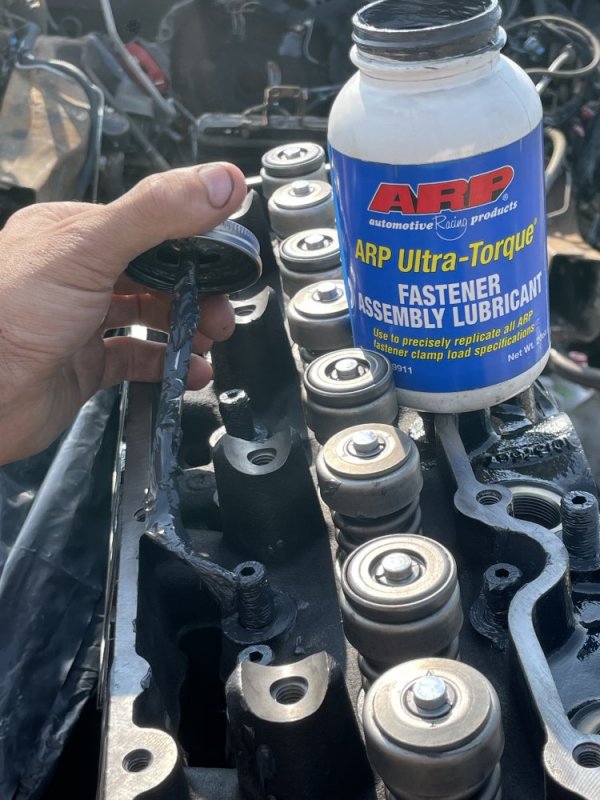
ARP fastener lube was applied to all contacting surfaces.
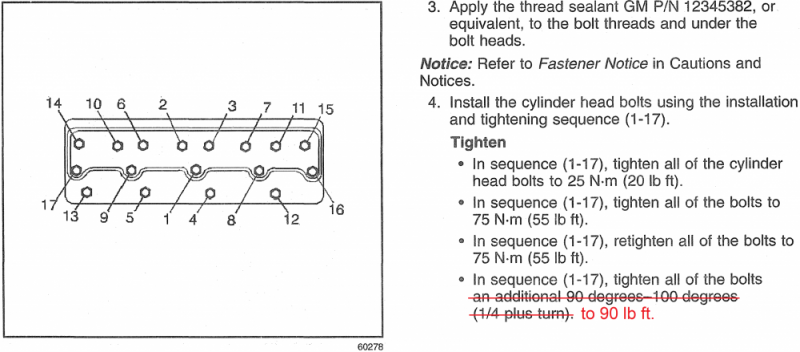
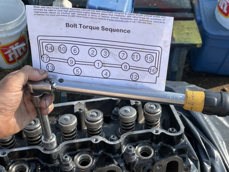
I referred to the 1998 C/K Truck Manual and the ARP instructions, and proceeded with the following torque and sequence:
Once the head was installed, I installed the injectors with high-temp anti-seize compound and new crush washers. The injector housings are Bosch and were rebuilt with Bosch nozzles by Vimy Diesel injection in May for ~$700CAD.
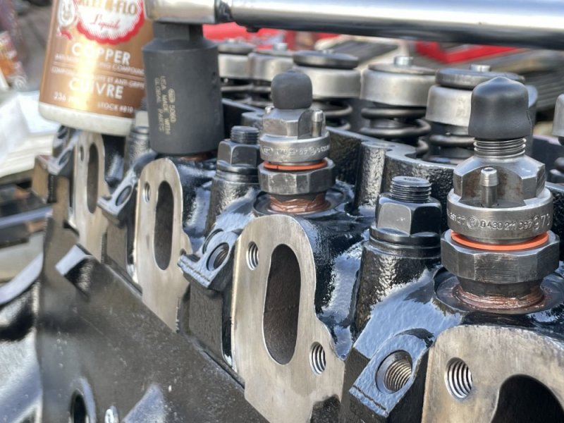
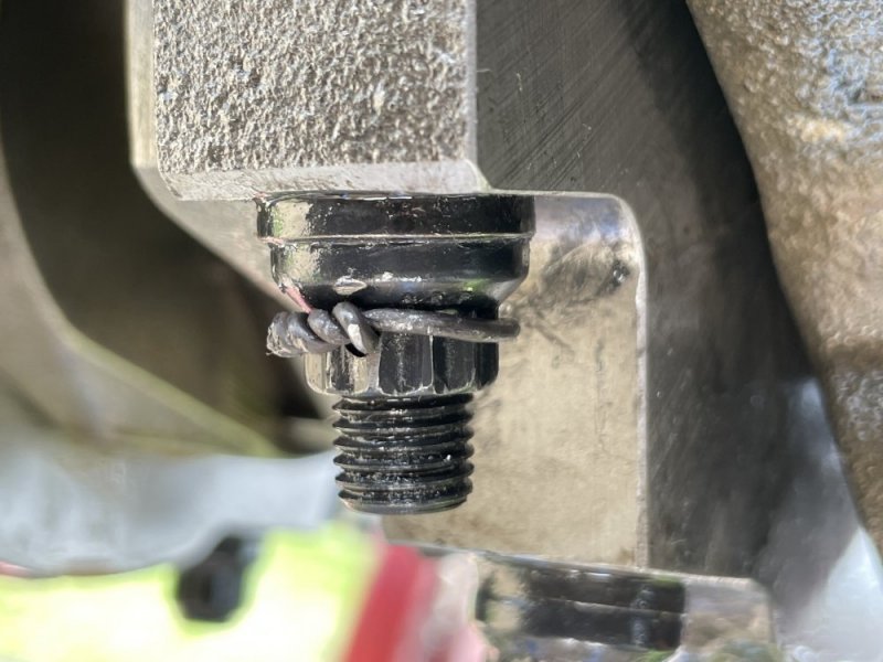
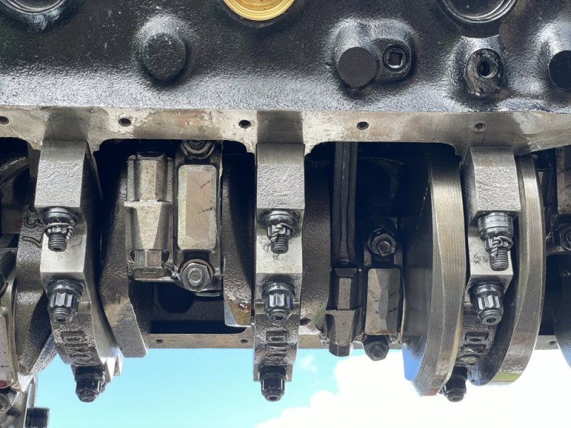
Tomorrow I will prepare the other side, and possibly fabricate a jig for drilling aircraft safety wire through the main nuts.


Once the surfaces were confirmed to be within spec, I swabbed the block threads with a Q-tip and Permatex Maximum Temperature thread sealant. I previously chased the threads with ARP chasers and swabbed them clean earlier in the week. I coated the coarse threads of the studs with sealant as well and screwed them in hand tight, wiped away the excess from the block surface, then again ensured the rest of the block surface was clean.

Since my heads were decked once before, I installed a 0.010" thicker gasket. Mahle 4021T .

ARP fastener lube was applied to all contacting surfaces.

I referred to the 1998 C/K Truck Manual and the ARP instructions, and proceeded with the following torque and sequence:


Once the head was installed, I installed the injectors with high-temp anti-seize compound and new crush washers. The injector housings are Bosch and were rebuilt with Bosch nozzles by Vimy Diesel injection in May for ~$700CAD.

Tomorrow I will prepare the other side, and possibly fabricate a jig for drilling aircraft safety wire through the main nuts.
Last edited:
Will L.
Well-Known Member
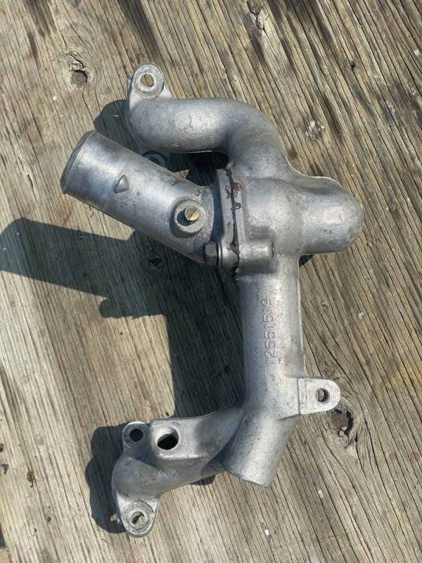
I see an unrestricted fitting in that waterpump. Are you running a single block off thermostat? If running the dual stat ya ought to get a restriction fitting in that pump.
lookin good man.
lookin good man.
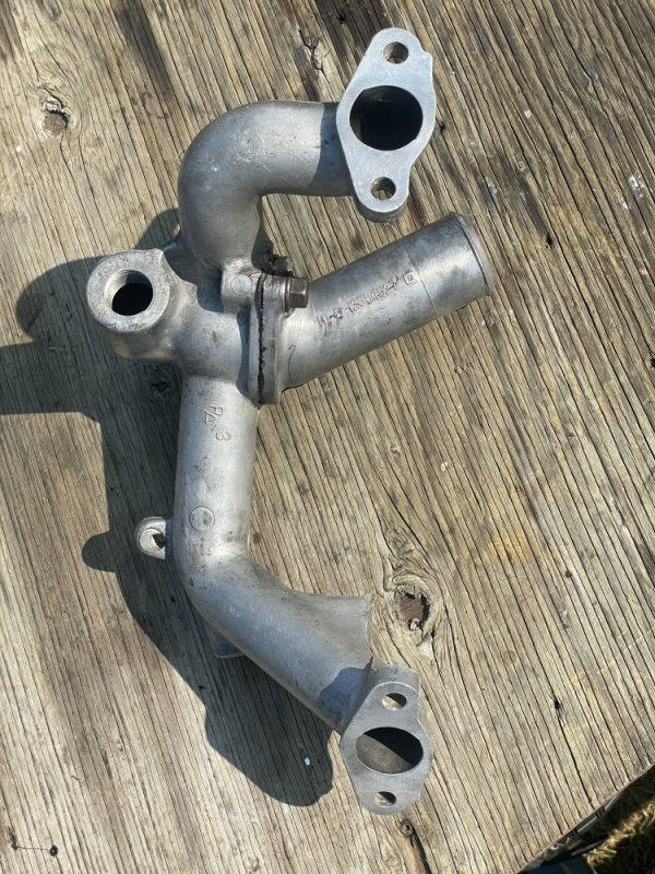
Thanks Will! Good eye. Yes I will be running a single block off thermostat from a '96, GM #12551519.
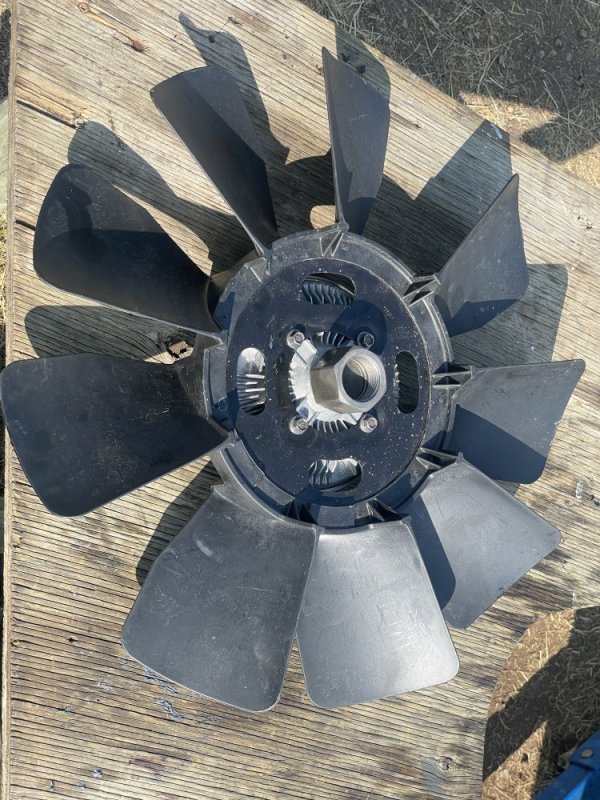
Followed Heath's article for cooling upgrades and purchased from RockAuto a new 190°F ACDelco thermostat, balanced w.pump, '00 fan clutch, and an LB7 Fan. I replaced the motor mounts with polyurethane and will trim the fan shrouds to fit the larger diameter fan.
Followed Heath's article for cooling upgrades and purchased from RockAuto a new 190°F ACDelco thermostat, balanced w.pump, '00 fan clutch, and an LB7 Fan. I replaced the motor mounts with polyurethane and will trim the fan shrouds to fit the larger diameter fan.
Attachments
Last edited:
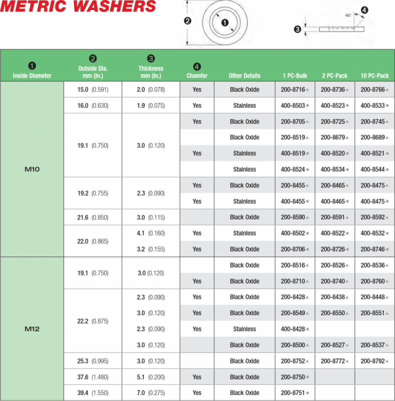
My 16mm head 12-point ARP nuts came in today. I also ordered another rear main seal, since I jumped the gun and installed it and probably should remove it to facilitate removal and replacement of the #5 cap fasteners.
If I am replacing all 20 nuts, I have to unload and reload the clamping of all the caps and I'm not sure how the rear main seal would affect loading of the cap 5, or if unloading and reloading cap 5 with the seal in place would cause the rear main seal to fail prematurely.
To remove the rear main seal without damaging it I would have to pull cap 5 at minimum. I'd rather not touch the caps because the pistons, timing, and valvetrain are installed meaning I can't easily spin the crank to determine if the bearings re-seated correctly or are binding.
My plan is to cut and pry out the rear main seal, replace the 12 and 14mm head ARP nuts with the 16mm ones, torque to spec, then install another rear main seal.
Last edited:
@Will L. I've been wondering in 3D how the safety wire will work. With elevation difference between the inner and outer bolts.
I'm considering using the wire on a second nut so the angle isn't too extreme. If the angle between the nuts is too extreme, the wire would roll over the head of the nut instead of wrapping around it.
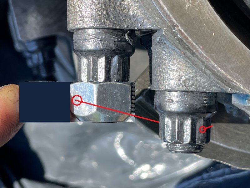
The angle issue is particularly noticeable with the splayed outer studs.
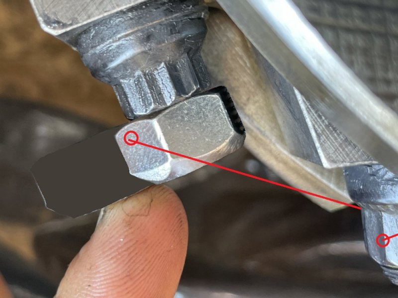
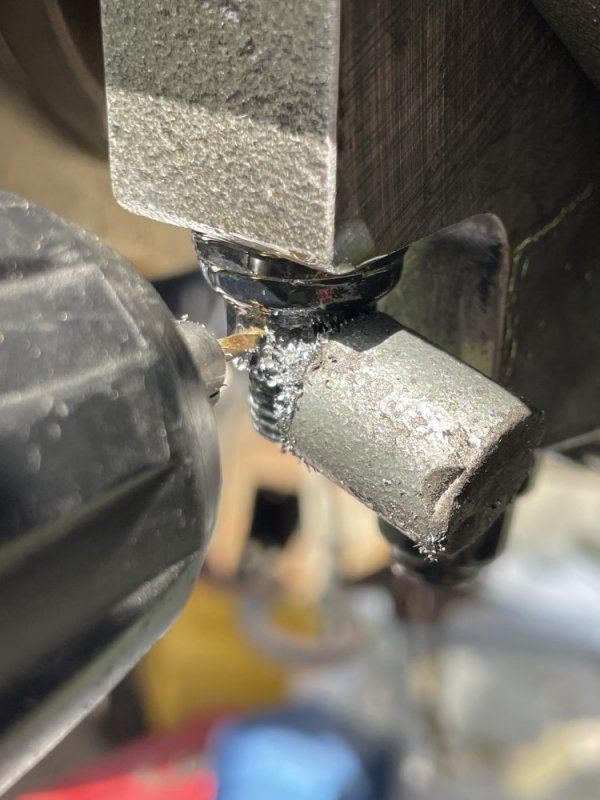
Maybe in my case it's safest to just drill a hole through the center of the M10 nut and stud, and thread it through and buy new nuts/studs on the following rebuild
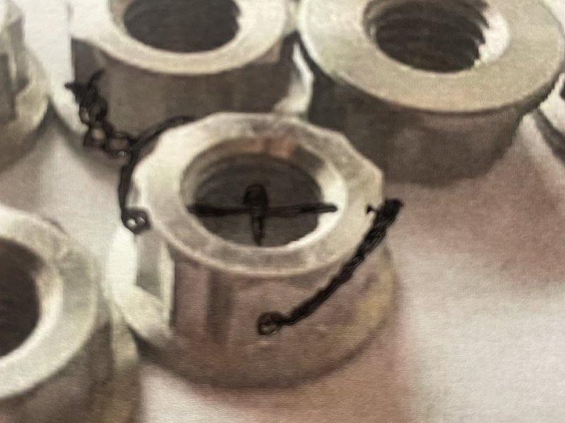
I'm considering using the wire on a second nut so the angle isn't too extreme. If the angle between the nuts is too extreme, the wire would roll over the head of the nut instead of wrapping around it.

The angle issue is particularly noticeable with the splayed outer studs.

Maybe in my case it's safest to just drill a hole through the center of the M10 nut and stud, and thread it through and buy new nuts/studs on the following rebuild

Will L.
Well-Known Member
If you don’t mind drilling through the stud with the engine assembled, it is better to through wire. You could then pre drill nuts.
If willing to drill through the stud after final torque, (then don’t really need the thicker nuts).
I just haven’t brought myself to drilling there on an engine assembled to that point. I am the guy that freaks out if someone uses lint bearing rags during assembly, so metal shavings is like torture. Some N52 magnets and physical shields maybe? Obviously engine stand rotated for all precautions available. Air compressor blower on during drilling?
If you do a chisel mark on the end of the studs indicating hole placement, you could drill new nut each replacement during rebuild and not need to redrill studs.
I expected a bit of an angle between the two, but didn’t think about the more severe angle you have with the splayed.
Last edited:
MrMarty51
Well-Known Member
You drilled through the stud too ?
n8in8or
I never met a project I didn’t like
I just had a thought, and maybe it's not an issue, but I figured I'd bring it up anyway. I agree that the safety wire is a great idea for making sure that the nut doesn't loosen and spin off the lubricated stud.......but now, what's going to stop the stud from threading out of the block? Since we are installing these at a lower torque than specified, wouldn't there still be a possibility for the stud to unscrew out of the block due to the lower tension the stud has been put under and therefore less friction between the stud threads and the block threads? I know the threads in the block aren't lubricated, so they'll have less tendency to turn, but wouldn't the possibility still be there? Or maybe @Will L. you've discussed this already in one of your many talks with the ARP engineers and it isn't an issue? Sorry if this has been discussed already, I didn't go through the various threads this is discussed in before posting this because I'm currently "at work" 
Will L.
Well-Known Member
Yup! Haha. You nailed it. The studs being dry on install will keep it from easily backing out, along with the amount of threads in contact they said.
if living in paranoid world (or just visiting my hyper paranoid world) use thread locker (loctite or similar) on threads in the block.
This of coarse led to me asking- “Wish you guys come up with a lube for torquing that when it dries becomes locking?” he says “well ya see...” 5 second pause “If the..umm...” 5 more seconds...then I hear pen scratches “DUDE, I am meeting with the other guys on zoom in a while and bringing that up.” So maybe a good solution coming 5 years from now...
Now, the other part of the lockwire is if you connect the two adjoining studs together it stops rotation of both nuts and studs. But the angle issue of the splayed mains makes that a problem.
On similar note there is a new designed nut that Hutchinson (they make military wheels and parts) has that uses double locknut combined with different angle than thread pitch (nordlock design) all built into the nut. That system may become more popular in another 10 years for many things.
n8in8or
I never met a project I didn’t like
Ok cool. I thought the thread-locker in the block threads was a no-no, but I must be remembering that wrong.
At work, we had a scenario where we were bolting a seat to a support using 7/16-20 stainless hardware. The initial design used a nylon-insert locking nut to secure the connection. You can imagine what happened more often than not - galling which led to either a loose connection or snapped fasteners. For a lot of our fasteners, we use a coating that is an aluminum-rich epoxy that prevents corrosion really well and allows the fasteners to thread into carbon steel and aluminum without a galvanic reaction (we used to use stainless in aluminum and ended up with galvanic corrosion issues there that would cause our powdercoat to peel). Unfortunately, this particular connection we were working on, was through stainless steel tabs and that aluminum-rich epoxy doesn't play well with stainless steel, so we couldn't use that in this case. We contacted a company that our hardware supplier works with and they have a coating that does exactly what you were explaining: it lubricates during assembly and then locks once it sits. Pretty cool stuff. I doubt it could be used for these nuts (at least not without examining how it affects the torque of the fastener), but the technology is definitely out there.
Interesting.....here's the data sheet for the product. It doesn't say anything about lubricating, but when we contacted them to help us with our connection, this is what they specified and to my knowledge we haven't had any problems with galling since we started applying this to the hardware in 2011. pds_epoxy-lock.pdf (ndindustries.com)
I used permatex max temp thread sealant on the coarse threads of the outer studs, that should add resistance to the threads in the block when cured
ak diesel driver
6.5 driver
I can't imagine regular loc-tite not having some lube quality. Be interesting to test it
FellowTraveler
Well-Known Member
Enconal NORD locks would have been a better option than drilling those studs IMO...then again I'm a NORD LOCK freak.
MrMarty51
Well-Known Member
I too have always wondered about that theory.I can't imagine regular loc-tite not having some lube quality. Be interesting to test it
I believe that any thing added to the threads of a fastener will have1: the ability to lubricate threads and change the applicable thread torque so the fastener will be actually tighter than the specified torque, or, 2: create friction so that the fastener will not be torqued tight enough according to the specs. Such as something like a valve lapping compound.

