• Welcome to The Truck Stop! We see you haven't REGISTERED yet.

    Your truck knowledge is missing!
    • Registration is FREE , all we need is your birthday and email. (We don't share ANY data with ANYONE)
    • We have tons of knowledge here for your diesel truck!
    • Post your own topics and reply to existing threads to help others out!
    • NO ADS! The site is fully functional and ad free!
    CLICK HERE TO REGISTER!

    Problems registering? Click here to contact us!

    Already registered, but need a PASSWORD RESET? CLICK HERE TO RESET YOUR PASSWORD!

DS4 IP rebuild time(mechanical aspect only)

bison

Well-Known Member
Messages
5,701
Reaction score
144
Location
Near Peace River-Alberta
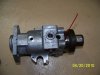
Ok fellows, gather around and watch us learn something about the internals of your IP

I took a DS4 5521 IP apart about a yr ago.Sorry no pics of that.
I managed to get my hands on a parts break down and spec sheet and some instructions how to stick the thing back together from a friendly pump mechanic.

Dismantling the pump is actually easy.
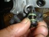
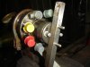
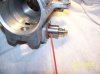
Lets start with removing the ESO + large spring, underneath is a plastic sleeve,and can be pulled out with a hooked tool .
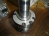
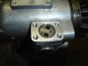
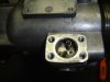
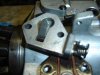
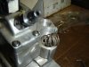
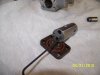
Remove the fuel intake nipple,then take the IP cover off,mark the OS location on the cam ring and remove the hold down bolt and the OS.
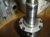
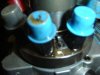
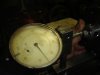
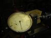
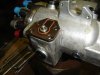
Next,figure out how to hold the hub without screwing it up and remove the nut, use a suitable puller and pop the hub off.

Note: if the pump can be turned easy by hand CC rotation,then the transfer pump is prob weak/worn or the key locking the pump hub to the input shaft is sheared off.

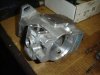
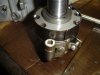
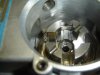
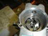
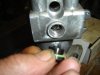
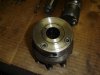
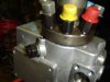
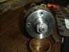
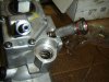
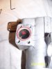
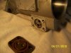
Remove the 3 bolts around the head and pull the head out of the housing,it'll come out as a unit.be carefull not to loose the 4 plungers in the rotor underneath as it comes free

Store all parts in clean diesel fuel,rust and dirt is your enemy.

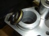
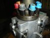
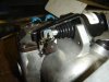
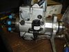
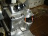
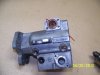
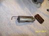
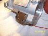
remove the stepper motor,and the advance cover with the spring.remove both side caps(there is 2 springs on the PMD side behind the cover) covering the advance piston and the plug in the bottom of the housing.Now pull the pin holding the advance piston to the camring out trough the hole in the bottom( a small magnet is helpfull).Push the piston from its bore(note wich side is to the camring).
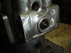
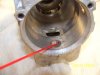
Remove the wavy spring and the camring from the housing.
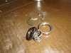
Remove the rollers with the shoes from the slots in the shaft(keep the rollers with their respective shoe's).
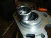
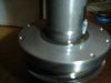
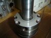
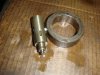
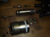
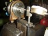
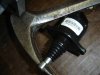
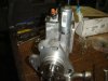
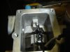
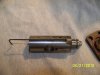
Remove the 2 bolts (outside of housing)holding the transfer pump in place and bump the shaft and TP as a unit from the bore. Be very carefull of the encoder/datatrack ring.
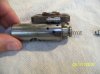
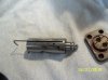
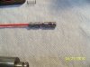
Set the shaft on end and remove the snap ring,the spacer and the small rollpin from the shaft(put a fitting drill bit or wire in the rollpin before using the pliers to pull it out, as the kit comes convieniently without it).

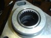
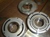
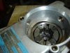
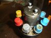
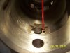
remove the 5 bolts holding the 3 pump segments together and lift the top 2 parts off( leave the middle section with the vanes together) .Remove the key and the bottom plate with needle brg.

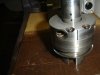
Use a fitting socket with extension and a hammer and bump both seals and the brg out trough the hub end of the housing.

The pump is now apart.
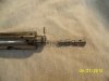
Onto the head.

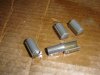
Remove the 4 plungers, 2 long,2 short.
Remove the little screw and clamp holding the FS in place.
Turn the FS CC wise off the head( may need to make a tool for that,will be shown later)

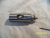
remove the crimp ring and the ring holder,push the rotor up from the bottom and remove the 2 keepers with their pins,be carefull they are small,remove the rotor.

Pull the spill valve and the spring out of the rotor.There is 1 or more tiny shims in the bottom of the bore,make sure you get them all,they are crucial so dont loose them.


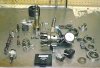
Here's a pic i took from the web that shows all the parts of the IP minus the housing.Prob illigal to post it :smile5:

you should maybe refrain from posting to this tread till i'm done,so we can keep it all together instead of it being strung out for 1/2 a ml.

more later
 

Attachments

  • dsparts.jpg
    dsparts.jpg
    38.8 KB · Views: 267
OK, done, mine is apart, next instructions please:D.

Skip the assembly part (just kidding) tell me how to adjust the Fuel solenoid then I will be happy, Oh and no rush: the dam pump has been apart for over a year. ):h:eek::sad:

If it is something super secret that will bring the law down on us pm me.
 
Chomping at the bit Slim):h

before we put it back together,wash all parts thouroughly with some sort of cleaning agent (i used a mix of diesel and diesel fuel conditioner cause thats all i had),
and blow it dry with an air gun.
Inspect all parts for scoring and galling,free movement and such so one can determine if the pump is worth rebuilding as hard parts are pretty expensive.
Submerge it all back in diesel fuel but the housing.

There are kits avalable,but they contain only 1 brg,3 seals , a crimp ring for the FS and a handfull of 0 rings.

In my kit there was 1 seal that was way to small and some 0 rings where leftovers and other ones needed where'nt there.No key,no rollpins,no backup rings .Mediocre at best.Not worth the money:nonod:
IMO Brgs,seals and 0 rings can be had at any decent supply store or a diesel shop,The only thing that is prob OEM is the crimp ring and the one tiny seal for the advance mechanisme,a diesel shop will have them too.

Pic 4) shows the bore with the bleed hole,the bore has a step slightly smaller below the hole so be carefull to select the proper seal for that spot. Press the seal (lip towards the inside) slightly past the step.I used a snug fitting socket to press the seal in ,if the shaft is grooved in that location one can push that seal in deeper so it rides on a new surface. Make sure the seal is perfectly square with the bore.
Then press the sec seal in(lip to the hub) below the surface and push it home with the new brg(flat side down)till the brg is flush or slightly below the surface.
Stick a wire trough the bleed hole to confirm its open between the seals.
The bleed hole is there in case of a blown inner seal to leak off fuel to the outside instead of it ending up in the crankcase.

More later
 

Attachments

  • DS4 5521 rebuild 004.jpg
    DS4 5521 rebuild 004.jpg
    41.7 KB · Views: 78
  • DS4 5521 rebuild 019.jpg
    DS4 5521 rebuild 019.jpg
    45.8 KB · Views: 74
  • DS4 5521 rebuild 020.jpg
    DS4 5521 rebuild 020.jpg
    46.6 KB · Views: 69
  • DS4 5521 rebuild 008.jpg
    DS4 5521 rebuild 008.jpg
    42.1 KB · Views: 74
Last edited:
Pic 1) tranferpump parts. backplate has a brg in it(second support for the shaft) and has 0 ring and backup/seal .The brg is part of the backplate and is not sold seperate(not in the kit either)The front cover has an 0 ring and backup seal as well(backups not in the kit)

2) Clean usable shaft,no wear on the brg and seal areas or on the roller shoe slots on the other end.

3) T pump backplate and key installed.

4) T pump and front cover installed and bolts in finger tight.The parts fit one way only and the pump and top cover are timed with the linear marks.Make sure the 0 rings/seals are in the grooves,they have a tendency not to cooperate,a little grease to hold them in place may help

5,6,7) rollpin, spacer and snapring in place.

8)now line the 3 pump segment up with a pison ring installer and torque the bolts down alternatly.
 

Attachments

  • DS4 5521 rebuild 009.jpg
    DS4 5521 rebuild 009.jpg
    54.5 KB · Views: 62
  • DS4 5521 rebuild 010.jpg
    DS4 5521 rebuild 010.jpg
    36.9 KB · Views: 60
  • DS4 5521 rebuild 011.jpg
    DS4 5521 rebuild 011.jpg
    30.2 KB · Views: 56
  • DS4 5521 rebuild 012.jpg
    DS4 5521 rebuild 012.jpg
    45.2 KB · Views: 52
  • DS4 5521 rebuild 013.jpg
    DS4 5521 rebuild 013.jpg
    48.7 KB · Views: 54
  • DS4 5521 rebuild 014.jpg
    DS4 5521 rebuild 014.jpg
    39.1 KB · Views: 57
  • DS4 5521 rebuild 015.jpg
    DS4 5521 rebuild 015.jpg
    41.1 KB · Views: 56
  • DS4 5521 rebuild 016.jpg
    DS4 5521 rebuild 016.jpg
    43.3 KB · Views: 56
1) pre oil the front brg and seals in the housing and install the shaft and T pump with T pump blind hole to the bottom. Note the timing mark/dot off center in the center of the shaft for line up to the rotor

2) install short hexbolt in the bottom to clamp the T pump to the housing.No seal on this one.

3) T pump outlet bolt with new 0 rings in this bore.

4) Camring and advance piston.The advance piston has a spring loaded valve that is operated by the stepper motor and has no 0 ring or seal. there is a step with a piston ring type mechanical seal (not in the kit either) I left it be,but it has to come off in order to get a pin out that holds the valve in place.
There is a reed valve on the opposite side.The reed valve is supposed to be slightly open what they told me.
The advance piston is operated by Tranfer pump pressure,the stepper motor controls the pressure to it.

5) cam(arrow to the bottom) and piston in place.Piston should slide smootly with no binding.

6) Piston pin trough the bottom hole and in the cam bore,ball end first

7 ) Plug to lock the piston pin.

8) ceramic rollers and shoe's.

9) Rollers and shoe's in place,rollers to the cam.
And the wavy washer/spring on top .

Rinse/dip all parts in clean diesel fuel before install.
 

Attachments

  • DS4 5521 rebuild 022.jpg
    DS4 5521 rebuild 022.jpg
    45 KB · Views: 55
  • DS4 5521 rebuild 023.jpg
    DS4 5521 rebuild 023.jpg
    43.8 KB · Views: 52
  • DS4 5521 rebuild 024.jpg
    DS4 5521 rebuild 024.jpg
    45.6 KB · Views: 55
  • DS4 5521 rebuild 025.jpg
    DS4 5521 rebuild 025.jpg
    57.5 KB · Views: 54
  • DS4 5521 rebuild 028.jpg
    DS4 5521 rebuild 028.jpg
    40.4 KB · Views: 54
  • DS4 5521 rebuild 026.jpg
    DS4 5521 rebuild 026.jpg
    41.7 KB · Views: 51
  • DS4 5521 rebuild 027.jpg
    DS4 5521 rebuild 027.jpg
    47.4 KB · Views: 50
  • DS4 5521 rebuild 029.jpg
    DS4 5521 rebuild 029.jpg
    50.4 KB · Views: 55
  • DS4 5521 rebuild 030.jpg
    DS4 5521 rebuild 030.jpg
    39.1 KB · Views: 53
When do we get to the solenoid adjustment, ARE WE THERE YET? ARE WE THERE YET? ARE WE THERE YET? ARE WE THERE YET?

Now ? Waiting patiently :D
 
When do we get to the solenoid adjustment, ARE WE THERE YET? ARE WE THERE YET? ARE WE THERE YET? ARE WE THERE YET?

Now ? Waiting patiently :D

Yes, Waiting-Waiting

Slim has one of my pumps as well removed last Sept. I was gonna send it out to a shop, but I'd rather pay one of our own guys to rebuild it.

The solenoid adjustment is going to be interesting as that is set with a bench flow check normally, but if we can come up with a working nominal setting that works, that would be awesome.
The sol adjustment cant be set with IP running on the bench.:nonod:

I'ts really realy simple once you know how:smile5:
 
More stuff.

1) Head parts.
In each injection outlet is a delivery valve,spring,stop with snubber, a small spring and a retaining screw,(in that order,topmost items).

left of the rotor,2 shims(amount varies with pump),a spring and a poppet/spill valve.

the rotor and plungers and the fuel solenoid.

The rotor is a select fit in the head and should slide and turn freely and fall out under its own weight,Dont put it in the bore dry or it'll seize. They are not interchangable, rotor and head only sold as a unit(very expensive)

The plungers ,2 long,2 short should also move easy in the rotor and fall out under their own weight.These are available seperate but there are diff lenghts avalable for various aplications.

2)There's 2 valves in the heads face,1 is a piston accumulator(PMD side) the other an accumulator spill valve. I think they are both for the advance?

3) two Rotor retainers, 2 locking pins, crush ring retainer and crush ring( on top of spring,Spring is only to show the ring,it dont belong in this break down.

4) Rotor in place,Fuel sol installed hand tight.
Sorry:eek: in the heat of the moment i must've forgotten to take pics how to put the parts together:mad2:

Anyway ,dip the rotor in fuel and slide it in the bore,on sol side put the 2 retainers bevel side down in the rotor groove and let it down in the recess in the head, line up the holes ,put the 2 pins trough the holes in the retainers and in te head,next place the crush ring retainer( tabs down) on the pins and place the crush ring in the retainer groove.

tread the shim(s) on a thin wire and drop them in the center hole of the rotor,spring next,then the spill valve( make sure it seats with the internal slots over the key in the bore).

put an new 0 ring on the Solenoid, give the ring a lick of grease and tread it in the head as far as it'll go by hand.

5) what some of you've been waiting for impatiently:smile5: The genie comes outa the bottle.

You've got to build an adapter to hold the micrometer steady to the head in relation to the rotor. I used an exhaust pipe clamp as you can see in the pic.But other means are OK as long as it is rock solid and perpendiculair to the rotor

Now put the micro gauge up to the rotor with the needle deflecting a turn or so and clamp it down. Push the rotor in as far as it'll go against the springload,hold it there and zero the needle,now let the rotor slowly settle back,note the amount of needle deflection.

6) Turn the Fuel sol in a bit with a spanner wrench( i made one from a piece of keystock and two 3/16 pins) and push the rotor back again,watch the needle deflection. Zero changes constantly and the needle deflects less and less as you turn the FS deeper in the head.
keep adjusting the FS and checking the needle by pushing the rotor in and let go till you got exactly 5 thousands of an inch needle deflection.
pics 7-8

Specs allow +/- 2 thou, 5 thousands of an inch is ideal.
This is the maximum lift the spill valve will open.

Now you'all know how it's done. simple actually:smile5:

9) rotor timing mark(dimple on the offset key) and plungers in,long plungers across the offset key.

10) Put a new greased 0 ring on the head the push the head in place keeping it straight up so the plungers dont slide out( a lick of grease will help here as well.keep the rotor and armature timing marks lined up,You might have to turn the hub a wee bit either way to let the rotors key engage the shaft slot.
FS clamp screw hole facing stepper motor mounting pad.
And bolts with new 0 rings installed in their respective holes .

11) note the bolt with screw on the PMD side,it provides a test port to measure the Transfer pump pressure.

12) FS clamp and screw installed.

Torque values come later.
 

Attachments

  • DS4 5521 rebuild 017.jpg
    DS4 5521 rebuild 017.jpg
    49.8 KB · Views: 76
  • DS4 5521 rebuild 018.jpg
    DS4 5521 rebuild 018.jpg
    37.9 KB · Views: 71
  • DS4 5521 rebuild 032.jpg
    DS4 5521 rebuild 032.jpg
    54.5 KB · Views: 69
  • DS4 5521 rebuild 034.jpg
    DS4 5521 rebuild 034.jpg
    38.9 KB · Views: 69
  • DS4 5521 rebuild 043.jpg
    DS4 5521 rebuild 043.jpg
    49.3 KB · Views: 73
  • DS4 5521 rebuild 040.jpg
    DS4 5521 rebuild 040.jpg
    38.2 KB · Views: 72
  • DS4 5521 rebuild 052.jpg
    DS4 5521 rebuild 052.jpg
    43.6 KB · Views: 72
  • DS4 5521 rebuild 051.jpg
    DS4 5521 rebuild 051.jpg
    45.1 KB · Views: 72
  • DS4 5521 rebuild 050.jpg
    DS4 5521 rebuild 050.jpg
    41.2 KB · Views: 68
  • DS4 5521 rebuild 049.jpg
    DS4 5521 rebuild 049.jpg
    42.8 KB · Views: 70
  • DS4 5521 rebuild 042.jpg
    DS4 5521 rebuild 042.jpg
    33 KB · Views: 75
  • DS4 5521 rebuild 041.jpg
    DS4 5521 rebuild 041.jpg
    32.2 KB · Views: 78
Last edited:
Thanks very interesting.

So what seems to be the worst wear points or which affect performance the most: plunger/rotor/head - clearance, fuel solenoid plunger, or other?

Which seals seem to be stressed the most? How does lift pump pressure affect things?
 
finnishing up.

Pic 1, The reed valve on the PMD side of the advance valve.

2) two springs go in corresponding holes in the piston.
The cover plate has two holes in it it as well,but do not line up with the springs in any position,but the springs seat against the flats between them(i failed to take a pic of that)

3) Advance piston cover plate installed. I used a needle nosed pliers to compress the mechanical seal to guide the piston in the cover.

4,5,6) The second cover with spring loaded lever that operates the adv piston spool valve, stepper motor,installed

7) Optical sensor in place( this IP came with the OS removed,but without the clamp and bolt,so i had to fashion something to bolt it down)
The initial setting is normally set with a gauge tool( wich i dont have) but my source told me to set it initially dead center to start with and move it over to the PMD for more fuel(pretty skimpy info).

I got an other spare IP(good one),so i took the cover off an measured with a feeler gauge between the OS and the housing,i came up with 2.35 mm clearance and I set the other OS to that clearance as well.
A fitting drillbit or allen wrench passed trough the OS gauge bracket and up against the stop on the housing as in the pic should get a guy close.

8,9) Plastic sleeve in bottom of ESO bore,and spring.

10) Fuel inlet strainer/transfer pump pressure relief valve(needs o ring on the bottom as well,is not in pic i noticed).
And IP fuel outlet/ housing pressure relief valve installed

11) ESO installed

12( IP complete.

Some torque values.

Rotorhead bolts 28 ft lbs
Tranfer pump to housing 16 ft lbs
OS to Camring 200" lbs
Drive hub nut 55 ft lbs

Tranfer pump pressure at engine rpm
16 psi at 150 rpm
45 psi at 600 rpm
100-104 psi at 1500 rpm
143-147 psi at 3400 rpm

Housing pressure
7-16 psi

supply pressure 4.5 -5.5 psi.

Schiker has some good pics of the advance piston, and is invited to post them in this tread.

There is prob plenty i ommitted or forgot,so feel free to add comments or ask questions,I got some of my own as well.
 

Attachments

  • DS4 5521 rebuild 053.jpg
    DS4 5521 rebuild 053.jpg
    45.7 KB · Views: 54
  • DS4 5521 rebuild 054.jpg
    DS4 5521 rebuild 054.jpg
    44.2 KB · Views: 50
  • DS4 5521 rebuild 056.jpg
    DS4 5521 rebuild 056.jpg
    44.5 KB · Views: 47
  • DS4 5521 rebuild 065.jpg
    DS4 5521 rebuild 065.jpg
    37.6 KB · Views: 47
  • DS4 5521 rebuild 064.jpg
    DS4 5521 rebuild 064.jpg
    43.3 KB · Views: 45
  • DS4 5521 rebuild 057.jpg
    DS4 5521 rebuild 057.jpg
    38.9 KB · Views: 45
  • DS4 5521 rebuild 066.jpg
    DS4 5521 rebuild 066.jpg
    48.9 KB · Views: 50
  • DS4 5521 rebuild 063.jpg
    DS4 5521 rebuild 063.jpg
    42.5 KB · Views: 49
  • DS4 5521 rebuild 062.jpg
    DS4 5521 rebuild 062.jpg
    49.1 KB · Views: 48
  • DS4 5521 rebuild 061.jpg
    DS4 5521 rebuild 061.jpg
    41.2 KB · Views: 44
  • DS4 5521 rebuild 060.jpg
    DS4 5521 rebuild 060.jpg
    44.8 KB · Views: 50
  • DS4 5521 rebuild 059.jpg
    DS4 5521 rebuild 059.jpg
    42.6 KB · Views: 48
So have you been able to determine which parts are failing in our IPs with their starting issues?
I would have needed a pump displaying exactly that problem me thinks.
It could however be caused by just a couple drops of water trapped in the bottom of the advance piston bore freezing up and jamming the piston in the bore(they have a pretty close tolerance as well).Or blocking off an orifice.That might explain why this only seems to happen when it's freezing weather.
I opened up an other IP and the advance piston had a bit of rusty scuffing on the bottom suggesting water is/was present.

IMO the fuel in the advance mechanisme is captive,only moisture can find its way down,and once there its there to stay.
 
Here is another thread that I took several pics of internals of an IP and tried to show my understanding - thoughts on flow path of fuel through the IP:

http://www.thetruckstop.us/forum/showthread.php?t=17824 As I said in the other thread I have had no training on IP's so I probably have some things wrong but the jist of it should be ok here/there with corrections noted when I can.

Here is my interpretation of the Advance Piston:

Pic 1. Straw would be on charge side (at transfer pump pressure) in the distributor (head?).
Pic 2. A ported screw allows fuel to feed to this hole from pic 1. Also holds the head to body.
Pic 3. Drill path through IP body.
Pic 4. Advance piston bore path from pic 3.
Pic 5. The advance piston pulled out showing the hole/slot that lines up with pic 4 drill path.
Pic 6. Shows the eventual end path or exit of the fuel to the IP housing cavity underneath the cam ring to flush and return to the tank.
 

Attachments

  • ds-ip-advance-II 005.jpg
    ds-ip-advance-II 005.jpg
    41.5 KB · Views: 22
  • ds-ip-advance-II 002.jpg
    ds-ip-advance-II 002.jpg
    48.6 KB · Views: 22
  • ds-ip-advance-II 001.jpg
    ds-ip-advance-II 001.jpg
    39.3 KB · Views: 22
  • ds-ip-advance 002.jpg
    ds-ip-advance 002.jpg
    45.6 KB · Views: 22
  • ds-ip-advance-II 021.jpg
    ds-ip-advance-II 021.jpg
    48.2 KB · Views: 23
  • ds-ip-advance 001.jpg
    ds-ip-advance 001.jpg
    46.2 KB · Views: 25
Last edited:
The Advance piston: Thanks to Bison, 6.2turbo, and SmithvilleD they PM'ed with me on this and other thread to help me figure some things out better.(hopefully did not leave anyone out and of course lots of reading threads and posts from others) Again the jist of it should be correct but I am not saying I have it totally figured out.

Pic 1. The PMD side of IP showing cover of advance piston (AP) bore.
Pic 2. Cover off showing end of AP, reed valve and the holes are for springs IIRC. I figure the cover is machined symetrical so as not to be able to install upside down. Flats are for springs to push against holes are for screw head clearance. Raised parts are stops for end travel limit???
Pic 3. The end of the AP with reed valve loosened and pushed to side.
Pic 4,5,6. Allen wrench trying to show the holes in the AP go through to the other holes that are just drill paths for the spool valve the AP bore will seal off the holes in the side of the AP not completely but enough to compensate for.
Pic 7. The AP from top the 3 holes on other side. The seal ring removed there is a cross pin holding the spool valve slide in.
Pic 8. The spring, spool slide, and button the stepper motor flapper hits and pushes on the spool slide to control position.
Pic 9. Approximate alignment of the spool slide to the ports.
Pic 10 Just showing the spool slide and button etc are hollow so the stepper motor end of the bore won't hydro lock.

I figure the transfer pump pressurizes the PMD side by pressure is a function of RPM of transfer pump/engine Bison noted associated pressures above. The reed valve acts like a check valve and the stepper can control pressure bleed due to viscosity changes in fuel with feed back from optic sensor maybe and also provide cold start advance.
 

Attachments

  • ds-ip-advance-II 019.jpg
    ds-ip-advance-II 019.jpg
    52.1 KB · Views: 21
  • ds-ip-advance-II 017.jpg
    ds-ip-advance-II 017.jpg
    50.9 KB · Views: 21
  • ds-ip-advance-II 016.jpg
    ds-ip-advance-II 016.jpg
    51.9 KB · Views: 21
  • ds-ip-advance-II 013.jpg
    ds-ip-advance-II 013.jpg
    49.4 KB · Views: 21
  • ds-ip-advance-II 011.jpg
    ds-ip-advance-II 011.jpg
    48.9 KB · Views: 20
  • ds-ip-advance-II 012.jpg
    ds-ip-advance-II 012.jpg
    47.4 KB · Views: 21
  • ds-ip-advance-II 009.jpg
    ds-ip-advance-II 009.jpg
    46.6 KB · Views: 20
  • ds-ip-advance-II 007.jpg
    ds-ip-advance-II 007.jpg
    48.3 KB · Views: 20
  • ds-ip-advance-II 006.jpg
    ds-ip-advance-II 006.jpg
    47 KB · Views: 20
  • ds-ip-advance-II 020.jpg
    ds-ip-advance-II 020.jpg
    51.8 KB · Views: 19
Last edited:
Schiker,it Looks like there was some water in that pump,looking at the AP.

Now if one could tell me how to test a stepper motor i'll be happy.
I ohm'd pins A + D and B + C. 48 ohm on both.
Applying 12 v power to either set of pins does'nt make it turn any direction.
There's just a screw jack treaded in a magnet,the magnet is supposed to turn around raising or lowering the screw.
Its got to be a slow RPM motor cause its fairly course tread on the screw
 
Back
Top