
n8in8or
I never met a project I didn’t like
I am attempting to install brass tubes in the coolant passages between the valve bowls in my heads. I'm working on a pair of heads that don't have cracks yet, so it's more of a proactive thing. In an unrelated conversation @Will L. sent me this video that showed how to do it.
I purchased an extended 9.7mm drill bit from MSC and some 10mm OD, 1mm wall brass tubing off of Amazon. Last night was my first attempt at trying it in a junk head I had laying around. The first thing I noticed was that the 9.7mm drill bit didn't really remove any material, it just kind of cleaned the hole up. The first brass tube that I started driving in got kind of mushroomed while I was driving it in and turned into junk before it even got all the way into the hole. After that I tried making a better driver using some bolts that I turned down using a grinder and then cutting a square shoulder using my bandsaw (this is the best I could do without having access to a lathe). I got further this time, but progress stopped about 1.5" from getting the tube installed all the way. Oh and I also ground a slight chamfer on the outside of the second tube to help it install.


I'm wondering what the appropriate interference fit should be between this tube and the coolant passage. I feel like this is too tight and that's why I can't get it to install. Since the drill bit isn't really drilling a hole, I'm not sure what the ID of the passage is exactly all the way down, however if I use the drill size and the known tube OD I theoretically have .3mm (.0118') of interference. I did a quick Google search last night and didn't find much helpful info. I did find some info on McMaster-Carr for bronze bushings and for a 10mm OD bronze sleeve bushing they spec an interference fit of .03mm (.00118")…..significantly less interference. I'm wondering if I should be shooting for a hole size somewhere between those 2 values. I'm hoping someone on here has some first-hand experience with this or something similar and has some guidance on what the interference fit should be.
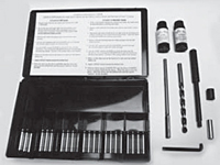
BTW, Lock n Stitch does sell a kit to do this job with their own inserts and reamer and driver, but it's a $400 kit.
I purchased an extended 9.7mm drill bit from MSC and some 10mm OD, 1mm wall brass tubing off of Amazon. Last night was my first attempt at trying it in a junk head I had laying around. The first thing I noticed was that the 9.7mm drill bit didn't really remove any material, it just kind of cleaned the hole up. The first brass tube that I started driving in got kind of mushroomed while I was driving it in and turned into junk before it even got all the way into the hole. After that I tried making a better driver using some bolts that I turned down using a grinder and then cutting a square shoulder using my bandsaw (this is the best I could do without having access to a lathe). I got further this time, but progress stopped about 1.5" from getting the tube installed all the way. Oh and I also ground a slight chamfer on the outside of the second tube to help it install.
I'm wondering what the appropriate interference fit should be between this tube and the coolant passage. I feel like this is too tight and that's why I can't get it to install. Since the drill bit isn't really drilling a hole, I'm not sure what the ID of the passage is exactly all the way down, however if I use the drill size and the known tube OD I theoretically have .3mm (.0118') of interference. I did a quick Google search last night and didn't find much helpful info. I did find some info on McMaster-Carr for bronze bushings and for a 10mm OD bronze sleeve bushing they spec an interference fit of .03mm (.00118")…..significantly less interference. I'm wondering if I should be shooting for a hole size somewhere between those 2 values. I'm hoping someone on here has some first-hand experience with this or something similar and has some guidance on what the interference fit should be.
BTW, Lock n Stitch does sell a kit to do this job with their own inserts and reamer and driver, but it's a $400 kit.
Order # L6269K, Diesel Head Water Passage Sleeve Kits On Lock-N-Stitch
Browse Order # L6269K, Diesel Head Water Passage Sleeve Kits in the Lock-N-Stitch catalog including Order #,Item Name,Description,Shipping Weight,Kit Contents (Replacements)
castingrepair.locknstitch.com


