• Welcome to The Truck Stop! We see you haven't REGISTERED yet.

    Your truck knowledge is missing!
    • Registration is FREE , all we need is your birthday and email. (We don't share ANY data with ANYONE)
    • We have tons of knowledge here for your diesel truck!
    • Post your own topics and reply to existing threads to help others out!
    • NO ADS! The site is fully functional and ad free!
    CLICK HERE TO REGISTER!

    Problems registering? Click here to contact us!

    Already registered, but need a PASSWORD RESET? CLICK HERE TO RESET YOUR PASSWORD!

99 Suburban 6.5 to 5.9 Cummins Swap

A 1st gen Cummins 2wd 4" OD downpipe attached to a mid-mount exhaust manifold will tuck down between the bottom two bolts of trans adapter on passenger side, another option would be a Cummins cobra-head down pipe.
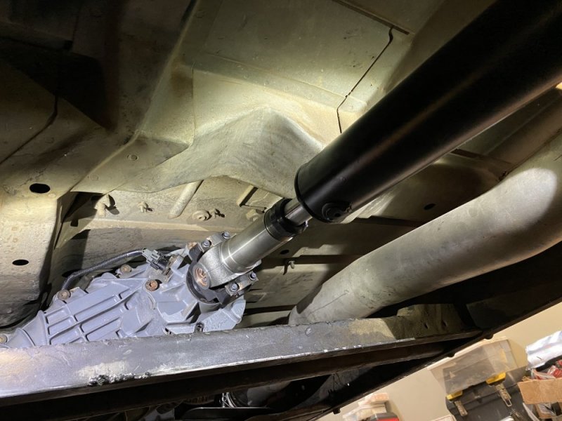
I'm running an HE351CW with a low-and-back exhaust manifold, and I already have a 4" stainless mandrel 90* attached to it still from the original downpipe I had built. Should be fairly simple for someone else to whip up a small section.
 
Don’t have the clutch starter safety wired in, but I do have the NSS wired up so it starts. Just waiting on driveshafts to show up from High Angle Driveline and I’ll be cruisin.

Also scored a stick diesel cluster. I wanted the completely refurbished one on eBay, but I couldn’t justify the extra $100.
 
Just got the cluster installed. Took it the new one apart, tried winding the tumbler for 30 minutes to match it with old, then realized I could just swap the “face” of the cluster assembly and entire tumbler.
 

Attachments

  • D3991CED-0ECD-45A4-9650-77273615D7FB.jpeg
    D3991CED-0ECD-45A4-9650-77273615D7FB.jpeg
    141.1 KB · Views: 14
  • 2CBEEA8E-4204-4615-BD23-A1E3B134998A.jpeg
    2CBEEA8E-4204-4615-BD23-A1E3B134998A.jpeg
    92.9 KB · Views: 14
I got rear driveshaft in and have been test driving it to make sure everything is squared away. One problem I’ve found, is the brake system is building pressure, and then they start dragging. The pedal eventually gets extremely stiff. My research has given me some possible culprits, as this has never happened before.
A) too much fluid in master cylinder
-I removed some fluid, had a minor affect
B) leaks in booster, needing a rebuild.
-I ordered a rebuild kit just in case, haven’t removed the MC yet.
C) booster pedal linkage is too long
-this seems plausible, as I swapped in a manual brake pedal, but I recall them having the same dimensions and proportions. I’m not sure if manual and automatics have different hydro boost units, I’d presume not.

which route would y’all go first?
 

Attachments

  • 46DDD4B4-AD3D-4A90-A99B-F3CBC3AE505D.jpeg
    46DDD4B4-AD3D-4A90-A99B-F3CBC3AE505D.jpeg
    125 KB · Views: 7
Can you reinstall the auto brake pedal and see what kind of freeplay you have and then make adjustments so the manual pedal has the same?
So I pulled the booster thinking I could easily replace the pedal push rod, wrong. Then I started taking a closer look at the pedals, and then remembered a YouTube video where he cuts the tread part of the pedals and swaps the small manual one onto the automatic. And what I noticed was the placement of the pushrod studs are different. I measured my old auto pedal and the ‘new’ manual pedal and the placemat of the studs is definitely different. See attached photo for comparison. I need this dumb think moving NOW so I guess I’m pulling the dash again to swap pedals. 🤦🏼‍♂️
 

Attachments

  • 9B8FD473-C640-42D6-A1B0-EAD480373C88.jpeg
    9B8FD473-C640-42D6-A1B0-EAD480373C88.jpeg
    74.5 KB · Views: 18
Too much brake fluid can NOT cause it. The volume from master to slave cylinders (or calipers) stays exactly the same regardless of amount in reservoir. If it is low, air can get drawn in.
If too full it will simply spill out the top lid seal. The system runs really high pressure and the lid seal barely holds a dozen psi at best.
 
For anyone thinking you can just swap pedals, this apparently makes a difference:
 

Attachments

  • 8347342F-2BB9-4F59-81E3-77E94850EA9A.jpeg
    8347342F-2BB9-4F59-81E3-77E94850EA9A.jpeg
    238.7 KB · Views: 10
  • 7F55B147-5ACD-4060-9B7E-75BAFEDE832B.jpeg
    7F55B147-5ACD-4060-9B7E-75BAFEDE832B.jpeg
    152.2 KB · Views: 10
  • 988F802A-B846-4BBC-BBCC-DBDABCDA3E13.jpeg
    988F802A-B846-4BBC-BBCC-DBDABCDA3E13.jpeg
    261.5 KB · Views: 10
  • E102521A-B014-4B06-8507-6199E72DEA67.jpeg
    E102521A-B014-4B06-8507-6199E72DEA67.jpeg
    171.5 KB · Views: 10
For anyone thinking you can just swap pedals, this apparently makes a difference:
The distance between the holes determines the pedal ratio...if I remember right "the rod from the pedal to the booster will have some play to compensate for the slight difference in angle".
 
Last edited:
Here is a helpful link for hydroboost...I rebuild my own hydroboost units simply because I have had nothing but bad results with rebuilt units from parts houses.
The most common problem "is dirt & other things like internal hose desegregation". One speck of sand can and will scratch the main piston causing leaks between the M/C & booster vent.
A hydro inline filter is best advice for sandy environments is it a vent filter which must be fabricated.
 
@FellowTraveler
Care to expand on the filter?
Well an inline hydro filter is made for high psi hydro systems and placed between the high pressure hose and booster.
The vent filter, is simply a fitting fit into the vent that is just a notch under the hydroboost where it meets the M/C. The notch can be filled in w/JB weld and dab of silicone rtv spread over the JB on the inside, this is to prevent brake fluid or p/s fluid compromising the JB material.
From here a hole needs to drilled close to where the notch was on the hydroboost and tapped for whatever fitting you would like to use finish off w/short hose and a $3 fuel filter or run up high and out of the way.

The other areas prone to sand ingress is the M/C when being serviced and the p/s steering pump when being filled.
 
Back
Top