• Welcome to The Truck Stop! We see you haven't REGISTERED yet.

    Your truck knowledge is missing!
    • Registration is FREE , all we need is your birthday and email. (We don't share ANY data with ANYONE)
    • We have tons of knowledge here for your diesel truck!
    • Post your own topics and reply to existing threads to help others out!
    • NO ADS! The site is fully functional and ad free!
    CLICK HERE TO REGISTER!

    Problems registering? Click here to contact us!

    Already registered, but need a PASSWORD RESET? CLICK HERE TO RESET YOUR PASSWORD!

4wd Actuator

Planned obsolescence. I believe all of the vehicles are rigged with what I call boobietraps, simple things that would fix a rig or keep it going, but the average Joe would in the manufactures eyes be more prone to go buy a new one. they saw their mistakes making rigs last 30+ years plus sharing the wealth of knowledge to us to fix them in our back yards and have slowly dwindled down their quality control and cheeping out on parts in hopes that the rigs won't even last 6-8 years now.

heck I wonder what their planned lifespan was for the High end Tesla. last I remember hearing is your lucky to get 100k out of one without major battery problems. and the battery costs more than the whole car!
Depending on the vehicle, Tesla warrants the battery for 8 years or 100/120/150K miles, but that is based on 70% available charge/range remaining. So in effect you're driving a car with constantly diminishing range. Somehow I don't think consumers would pay up for a gas-powered vehicle that would see continually worsening mileage or performance.
 
I don't get it. If GM knows and realizes the grounding is an issue then why don't they simply correct it? Make ground straps out of stainless steel and put them in several locations! That's probably what we all did. I know I did.
There were issues with conductivity with stainless on Manitowoc cranes.

I'm not sure why. But in places they were using stainless instead of brass or copper, the little bit of extra resistance caused issues.

I've used plenty of stainless and never had an issue
 
it could have been at the connection points. some dis-similar metals start corroding when electricity is passed through them at the connection points. I have only seen this on residential and commercial wiring but I suppose it can also happen with low voltage applications too.
 

Finally was able to pull some codes, though not sure is this was due to having the harness disconnected whilst I was doing tests.

C0310 - A/B Motor Circuit Open
C0323 - Transfer Case Circuit Low
C0327 - Encoder Circuit

Also:

U1041 - Lost communication with Electronic Brake Control Module
U1000 - Class 2 Data Link Malfunction
U1010 - Loss of PCM Communication

I cleared the codes and will drive it to see what appears again.
 
I ordered a set of back probes to do the remaining tests, but they will arrive Monday. It’s supposed to be below zero weather over the weekend through Tuesday, so I wasn’t going to be doing this work anyway. I’ll have the following weekend, then head down to SoCal on the 6th. They have hybrid work schedule and meaningful in person collaboration as part of my performance goals, so I anticipate significantly less time in Montana. Will probably have to move the Suburban down to SoCal to complete this job.
 
Starting at 15:05 in this video, I could not perform the tests he did for the A and B circuits, or I could not get power across them.


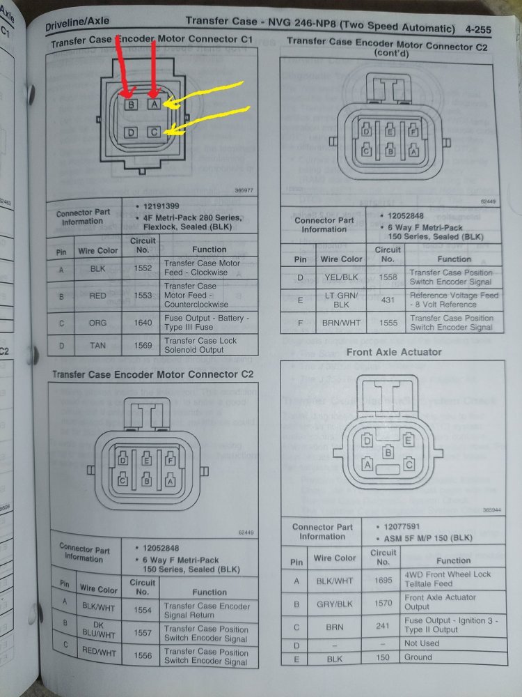
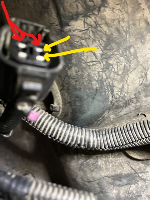
I get 12.54v at the yellow arrows when grounded to the frame. In his video he's commanding A and B circuits at the red arrows and getting a test light to work when connected there. I can't replicate that, but he was using his diagnostic tool to make the commands. I would have to explain to my wife how to do that, then have her do it while I'm under the truck. I need to fab up some test lights with probes like his.

View attachment 79113
1674749484402.png

Just to mark my progress against the manual, I've done the tests at the Transfer Case Encoder Motor Connector C1. I get 12.54v at the yellow arrows when grounded to the frame. I get nothing across A and B or when each is grounded to frame. Need back probes to test at C2, but really the problem is at A and B in the Encoder Motor Connector.

Transfer Case Encoder Motor Connector C1 Marked.jpg
 
Last edited:
Yeah, I wish the factory manual had either an actual picture, or at least a line drawing of, the location of the C131 and C132 connectors, but it only has the location description which I repeated verbatim. Guess it's time to dive under the dash and running the wire harnesses to find them! I guess GM figures that dealership mechanics already know where these connectors exist and the manual just provides a "reminder" for them where to look.
 
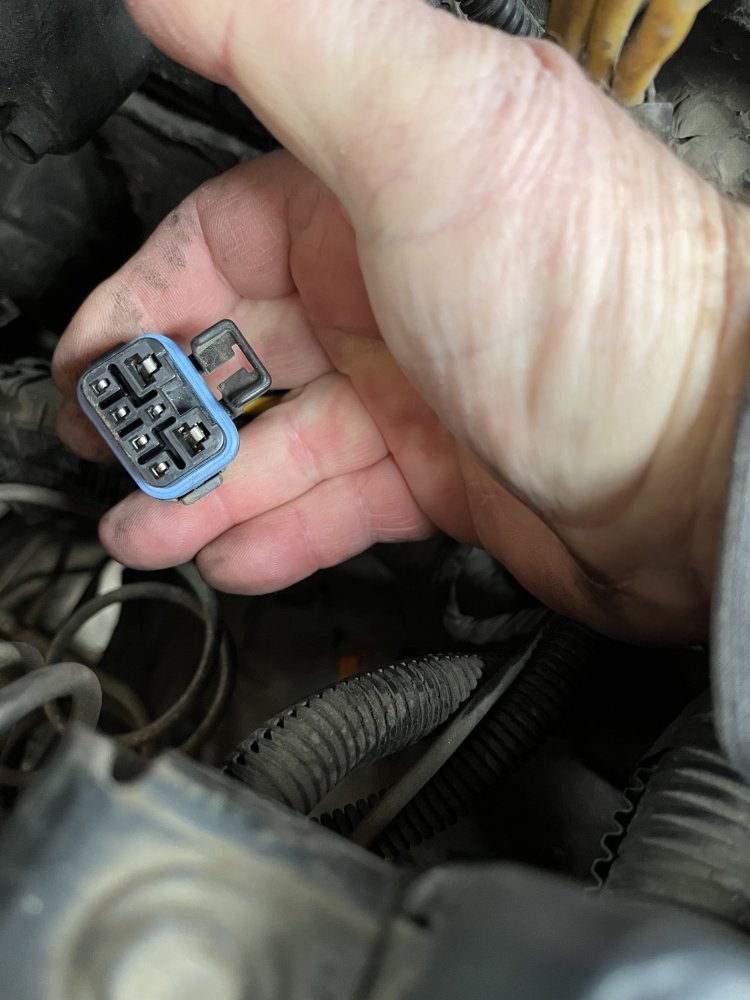
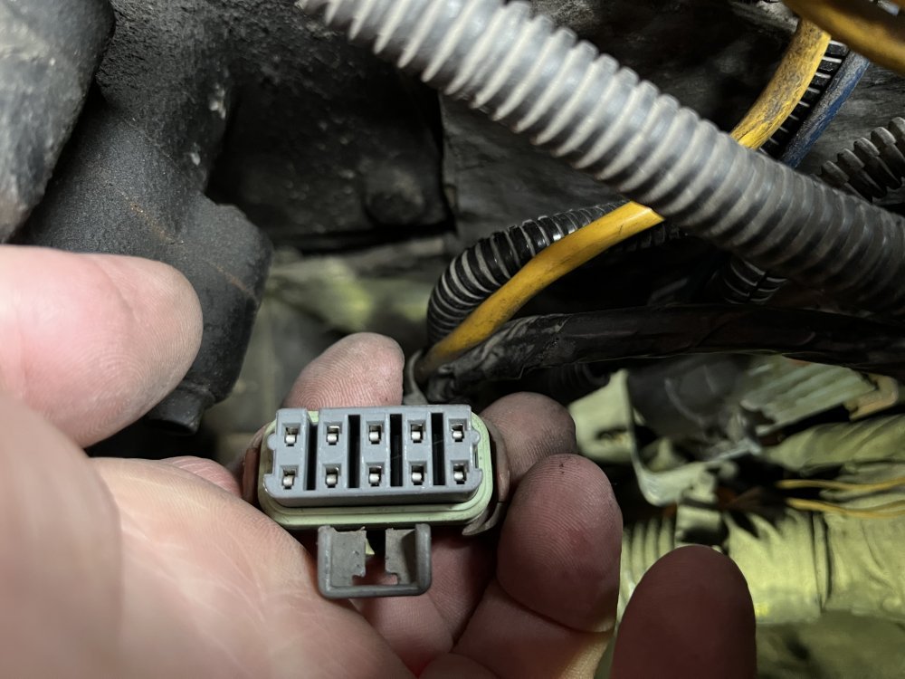
I went under the dash and took pictures of every plug, but none look like C131. Then I went into the engine compartment and found C131 which was directly under the hydroboost:

4501F45D-724A-4370-B2B5-A03BF2592C3B.jpeg

The leads from this female side of the connector head straight back along the frame towards the transfer case. It makes sense as prior instructions said to inspect C131 for corrosion or wire damage, and corrosion is unlikely for anything under the dash.

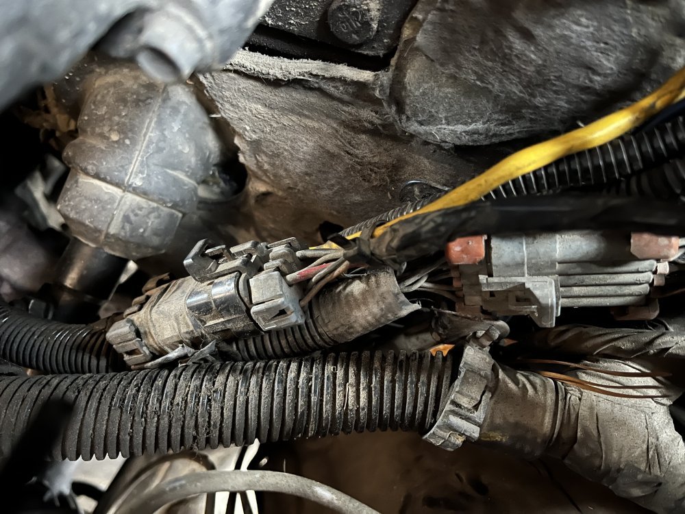
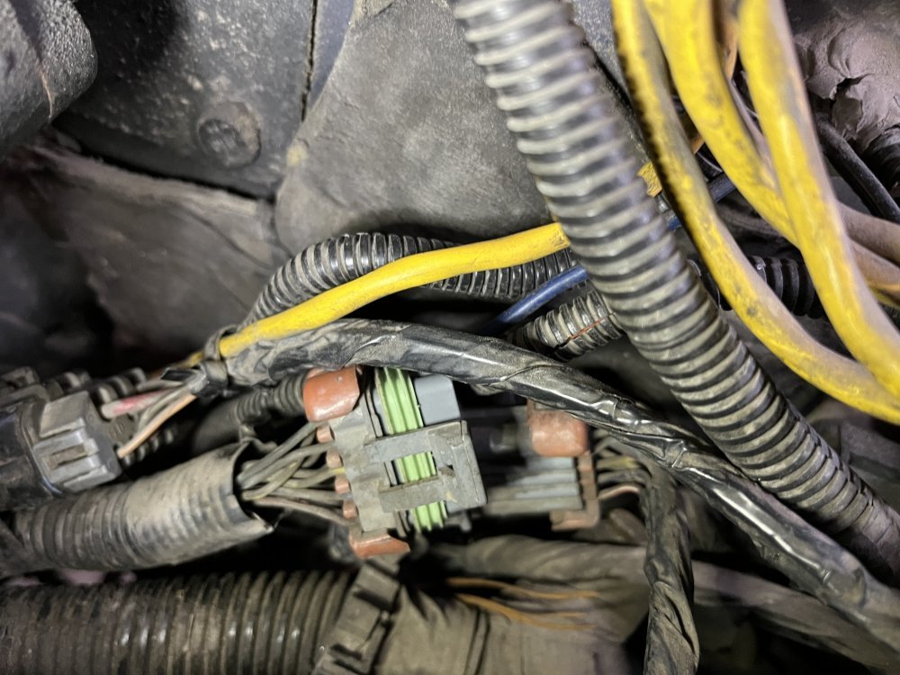
Also found C132, which is right next to C131:

748FDAB4-870A-420E-8BF2-0F2E924E6D11.jpeg
5B782E3B-B49D-4F5B-BF9A-6BF08C972438.jpegE47E450E-9E8C-4BE3-963E-5DD37EA2A107.jpeg
 
Last edited:
That's interesting, because the Zone Location diagram for connectors says that C-series connectors are located in the engine compartment, yet the printed location descriptor says that C131 is located under the dash in the harness. I guess a picture IS worth a thousand words! AND, it backs up what we used to say in the Army about TM Updates, "Pictures are for Warrant Officers only!"

Glad you found them. Some voltage checks may just help you isolate the problem. I belive I included the troubleshooting guides in those photos I posted. If not, I'll take pictures of the flow charts and post them up here. Laying on the ground in subzero weather is NOT fun!
 
Maybe I'm doing this wrong?

I unplugged C131 and C132, one at a time and turned ignition on. Tested both sides of the plugs with the test meter, selector switch on 2Hi and 4Hi, using the red probe on the plug terminals and black on battery ground. I never got any voltage.

These plugs come from the engine harness going across the back of the engine. Where is the voltage coming from? The PCM?

Also, I have no idea how to conduct continuity tests. Do I have to touch the probes to either end of the harness run?
 
Continuity is across each end of the harness run, using a self-powered continuity tester or a VOM set to its lowest resistance setting. Power for the actuators is from a fused battery source - no power is either an open in a harness, a blown fuse or a blown fusible link on a power source to that section of the fuse box the fuse is in. If you notice in one of those connector pin out diagrams, it shows the voltage being 8VDC. Also, I found that CD-ROM late last night, I will be dropping it in the mail First Class Postage and properly packaged to get it to you in a timely manner, tomorrow. I'll PM you with the postage amount.
 
Maybe I'm doing this wrong?

I unplugged C131 and C132, one at a time and turned ignition on. Tested both sides of the plugs with the test meter, selector switch on 2Hi and 4Hi, using the red probe on the plug terminals and black on battery ground. I never got any voltage.

These plugs come from the engine harness going across the back of the engine. Where is the voltage coming from? The PCM?

Also, I have no idea how to conduct continuity tests. Do I have to touch the probes to either end of the harness run?
I dont know where voltage is coming in from.
Continuity is a probe in pne end of the wire, probe the other end and hook meter to the probes on each end, ohms scale.
 
I THINK that 8V terminal is used to actuate the relay for 4LO, but without spending a bunch of time with the manual and the wiring diagram tracing that circuit across multiple pages, I can't be positive (no pun intended) about that. I think that terminal only gets 8V when the 4LO switch is engaged.
 
Back
Top