usanumber1
Well-Known Member
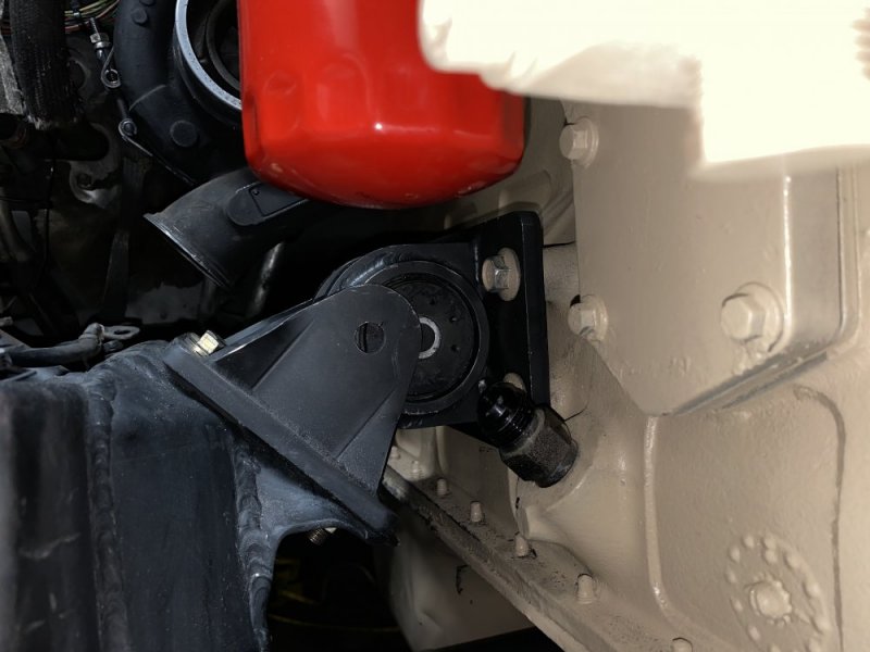
I got one side of my SSOR mounts installed last night. Driver side mount is in and connected to Block, used “long” mount for the driver, but it is a solid 1”+ horizontal gap before the holes will line up. Am I doing this wrong?