• Welcome to The Truck Stop! We see you haven't REGISTERED yet.

    Your truck knowledge is missing!
    • Registration is FREE , all we need is your birthday and email. (We don't share ANY data with ANYONE)
    • We have tons of knowledge here for your diesel truck!
    • Post your own topics and reply to existing threads to help others out!
    • NO ADS! The site is fully functional and ad free!
    CLICK HERE TO REGISTER!

    Problems registering? Click here to contact us!

    Already registered, but need a PASSWORD RESET? CLICK HERE TO RESET YOUR PASSWORD!

2008 GMC Envoy Denali

Slow progress this past week, but I’m sitting pretty good right now.

Rather than dive right into the short block I instead decided to start getting the truck ready to receive the drivetrain. So I reran harnesses and installed new power steering hoses and cooler. I also reinstalled all of the crossmembers I had removed for the frame derusting.
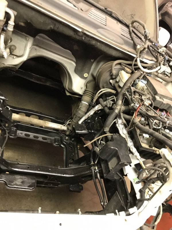
56430

I also have all new seals installed in the front diff and front intermediate shaft bearing.

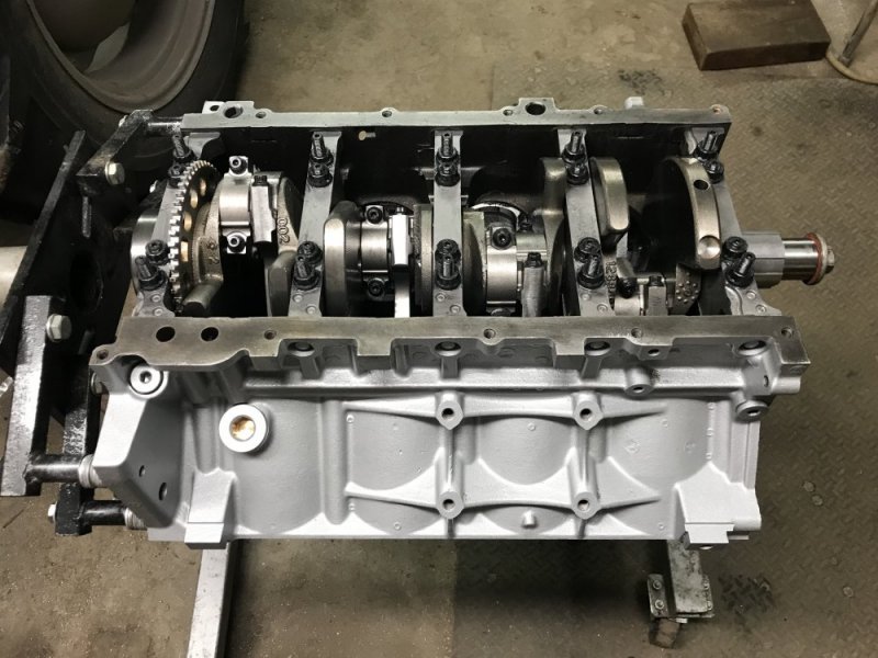
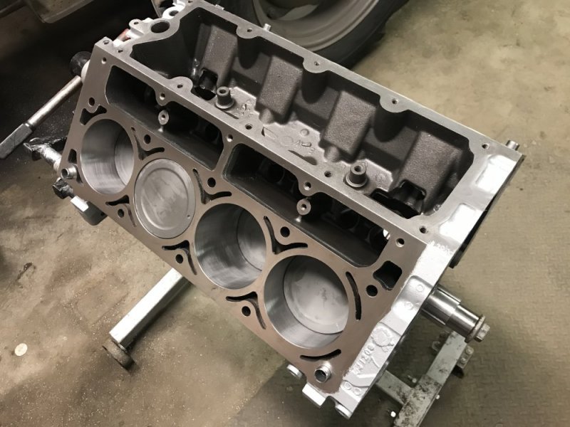
Then today I finally finished up the short block. I checked the ring gaps and connecting rod bearing clearances and got all the pistons and rods installed and torqued down. The rods are the later model floating rods that are stronger. I bought a set that had been refurbished by a place that sells them on eBay. Then I had the machine shop fit ARP rod bolts and hone them round again. These rods are a cracked cap design so they can’t resize the big end like a typical rod - they hone them .002” oversize and there is a special oversized bearing available to fit. My clearances were .002” on all of my jounals so everything was all good there. I went with the dished pistons so I can have a reasonable compression ratio to run 87 octane now and then later on I can swap heads and regap the rings and it’s ready for some turbo fun. The whole rotating assembly is balanced.
5642456425

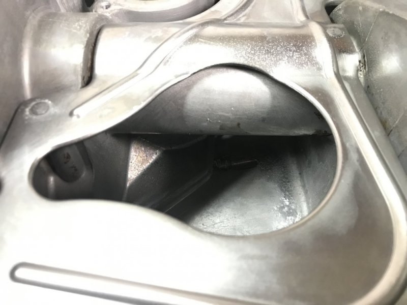
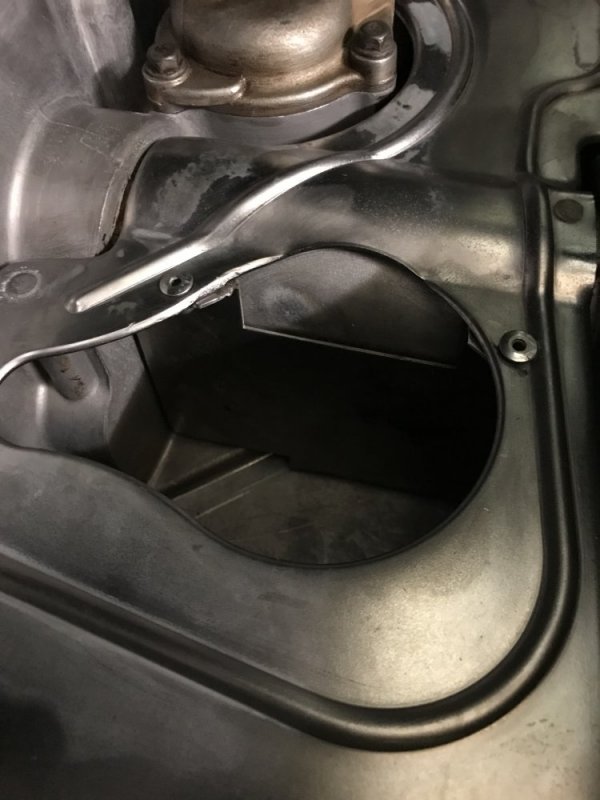
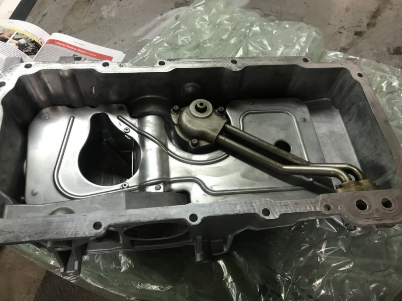
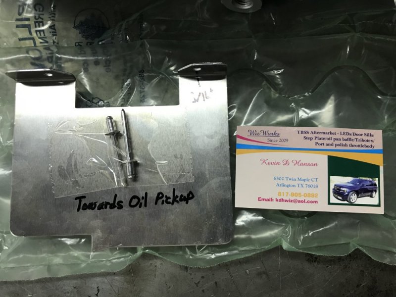
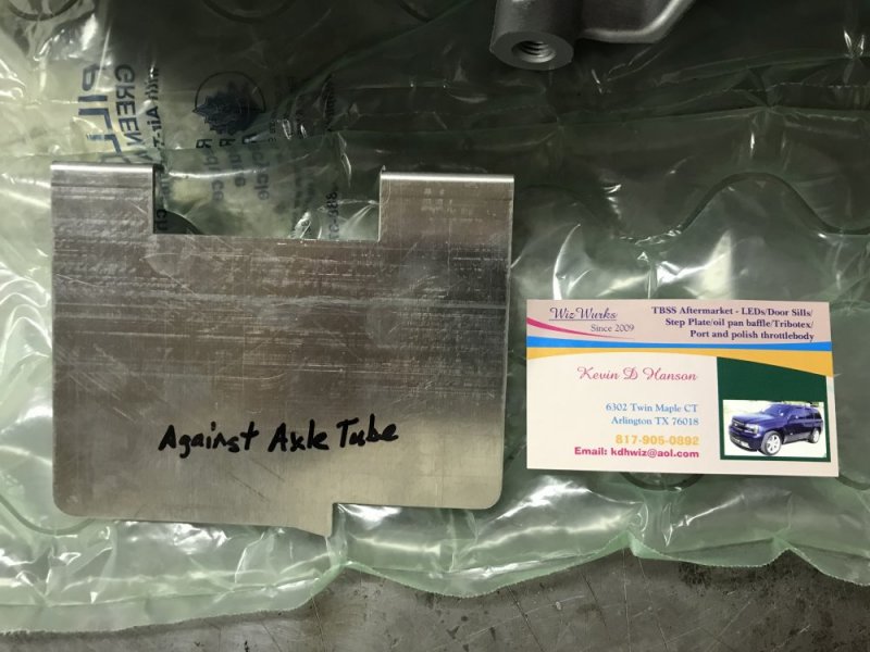
Next I started on the oil pan. This chassis has a front sump oil pan. Trailblazer SS’s have a problem with oil starvation on launch because the oil sloshes away from the oil pump pickup. For AWD/4WD, you can either buy a $300 extended pickup or a $25 baffle. I went with the baffle. So today I installed the baffle and replaced the gaskets for the oil filter adapter in the pan.
56426564275642856431
56429

The final thing I did was start replacing U-joints. The front shaft is done and the joints are removed from the rear shaft - I’ll install them tomorrow.

My cam is supposed to be coming in this week and the machine shop was also hoping to have my heads done by the end of the week. If both of those things actually happen and my piston-to-valve clearance is OK, I should have the engine assembled and the engine/trans installed next weekend. Then a couple more days of buttoning up and then it will be ready for tuning! I can finally see the light at the end of the tunnel. 🆒
 
Some you win and some you lose.......

I left the details of my cylinder head saga out of my earlier posts just for simplity's sake, but now it is time to share the details.

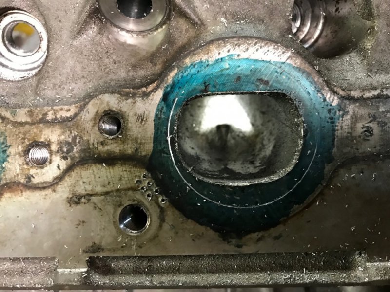
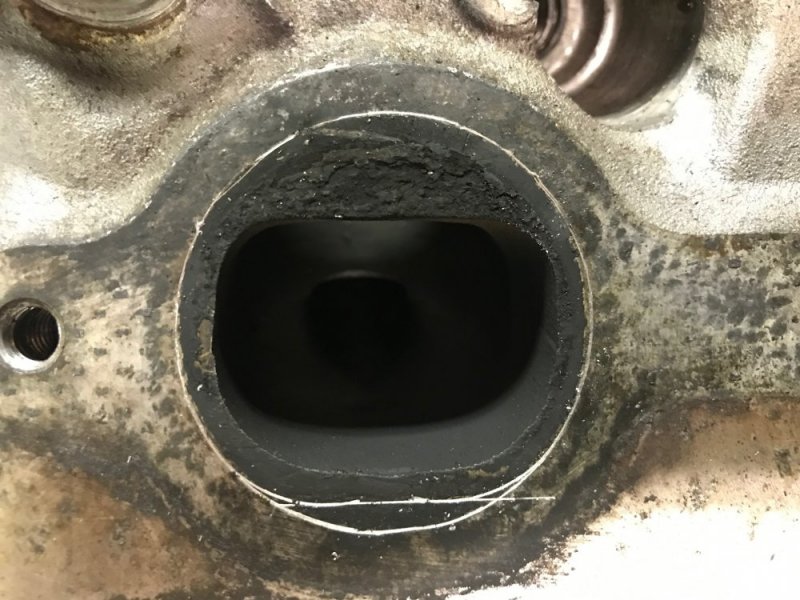
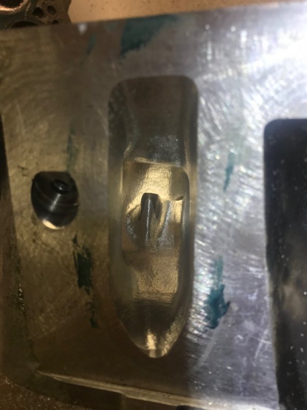
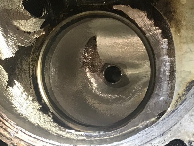
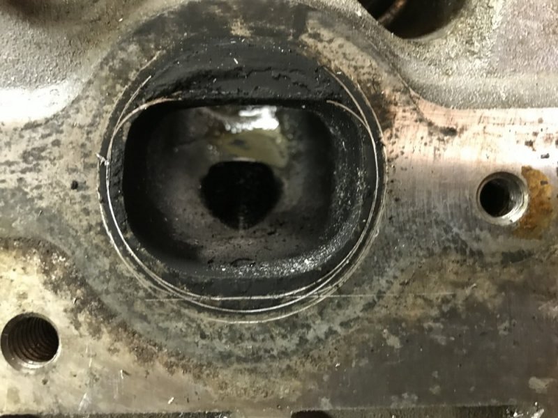
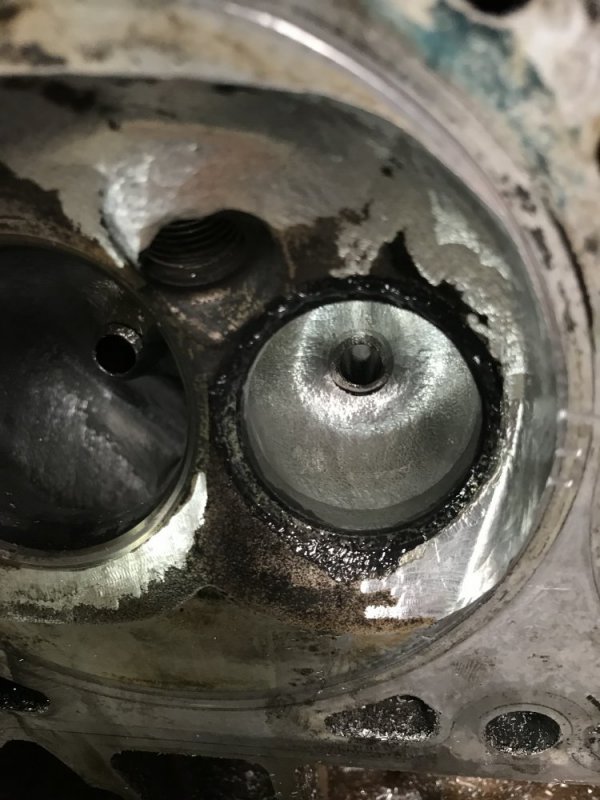
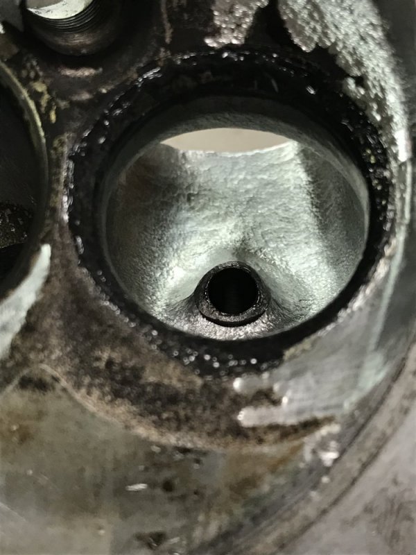
I made a mistake with the exhaust ports. I thought I was being smart by scribing the outline of the exhaust gasket
56482

and then porting to within .060 - .090".
56481

Once I did the first one, I was surprised at how big that made the opening and regretted that I did it - but only because I thought I made the port too large and killed velocity. Ah well, the deed was done so time to blend the rest of the port to the opening.

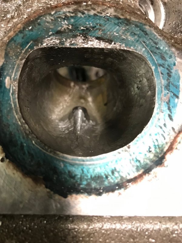
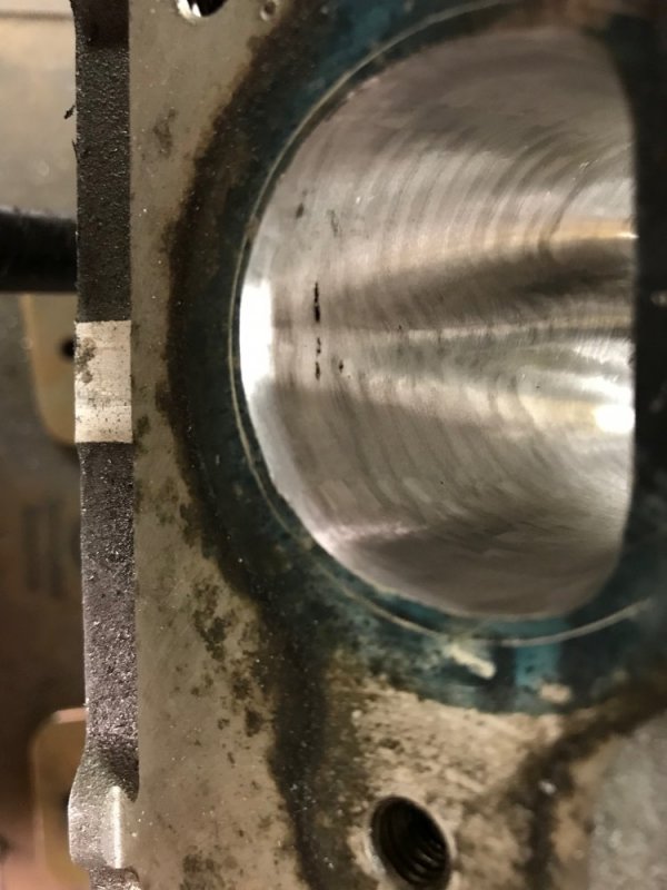
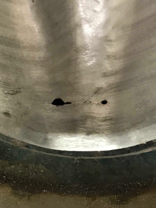
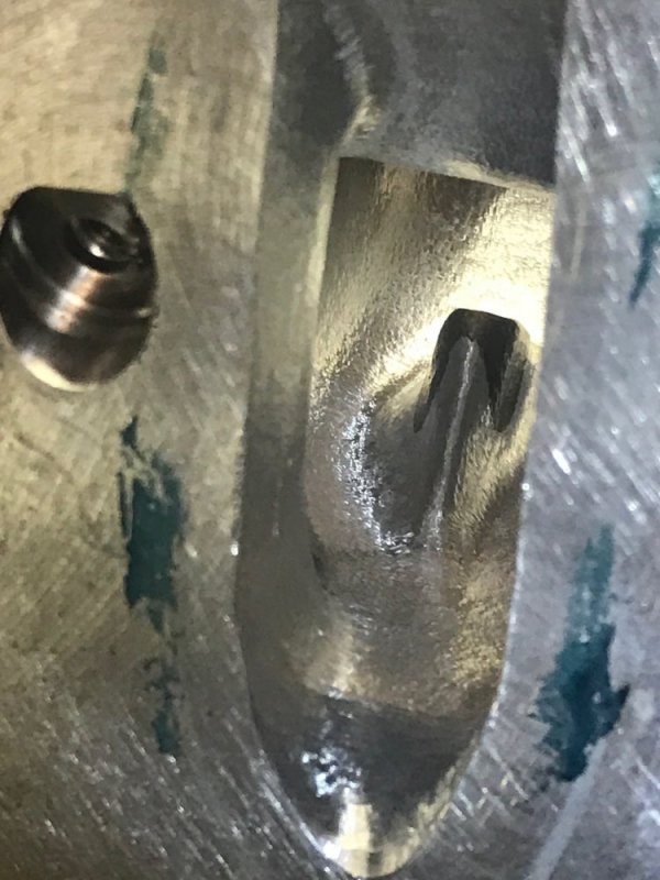
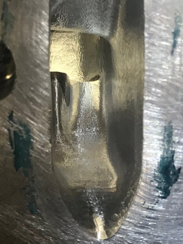
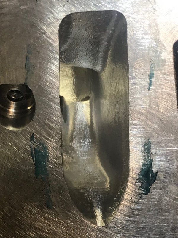
Well as I was finishing the ports with the cartridge rolls a small crack started to appear.
56478

I poked at it with a pick and sure enough, it was an opening into a void. Dammit!
56479

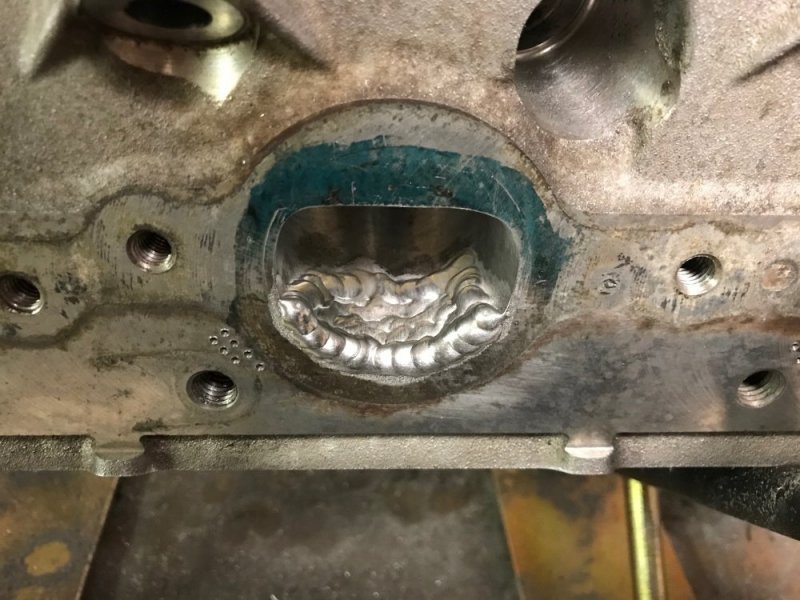
Come to find out, there is actually a small coolant passage above the exhaust port. From the outside of the casting it looks like it would be solid there. Oops. So I took my heads into work and asked a guy there to lay some beads in the port to build them back up.
56483

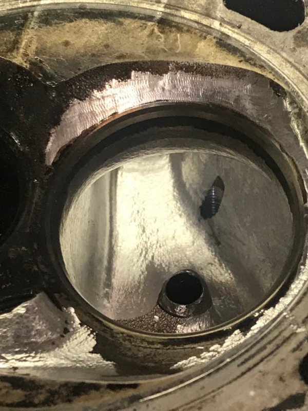
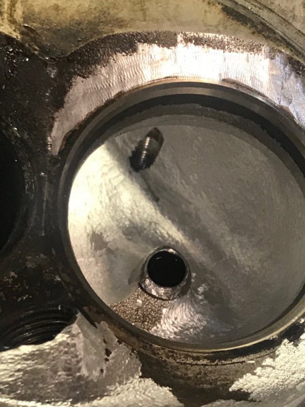
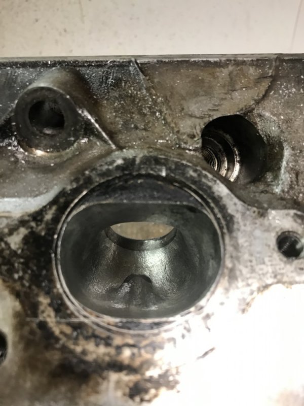
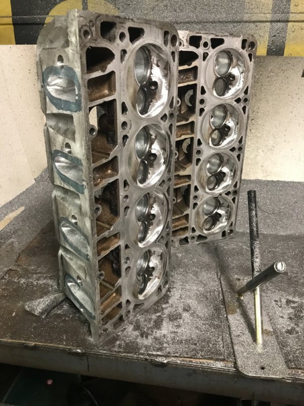
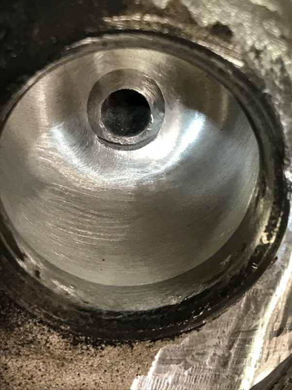
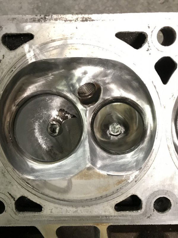
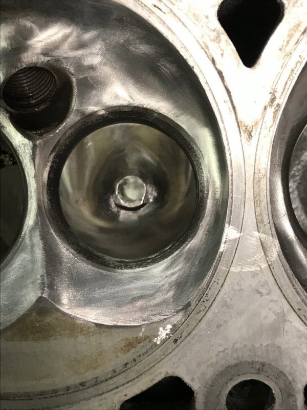
After multiple days of taking them to work then taking them home and grinding on them, and then taking them back into work for even more welding (I really need to get set up to weld aluminum at home!) I finally got to what I showed you in the finished ports.
56480

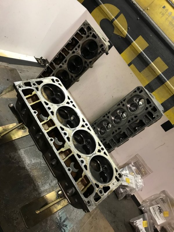
It was then that I took them to the machine shop to get a valve job done. I told them what I had done and asked them to pressure test the heads just to make sure they were ok.....good thing I did - I got a phone call from the machine shop last Wednesday that one head had 2 exhaust ports leaking and the other head had 1 exhaust port leaking. Some of the leaks you couldn't see any apparent defect in the head, but once under pressure they leaked. My first thought was to just start welding on them some more, but the machine shop was afraid that even if they looked good when the welding was done, who's to say something wouldn't open up once they start getting run and heat is applied to them? Their recommendation was to start over. Since this is going to be a daily driver that I also want to take on trips, I agreed that it was better to be safe than sorry. So that night I found a pair of 243 heads 30 minutes away from me. I contacted the seller and had them back at the house that night.
56485

One of the first things I did was scribe new lines on the exhaust ports. This time with a significant change.
56484
 
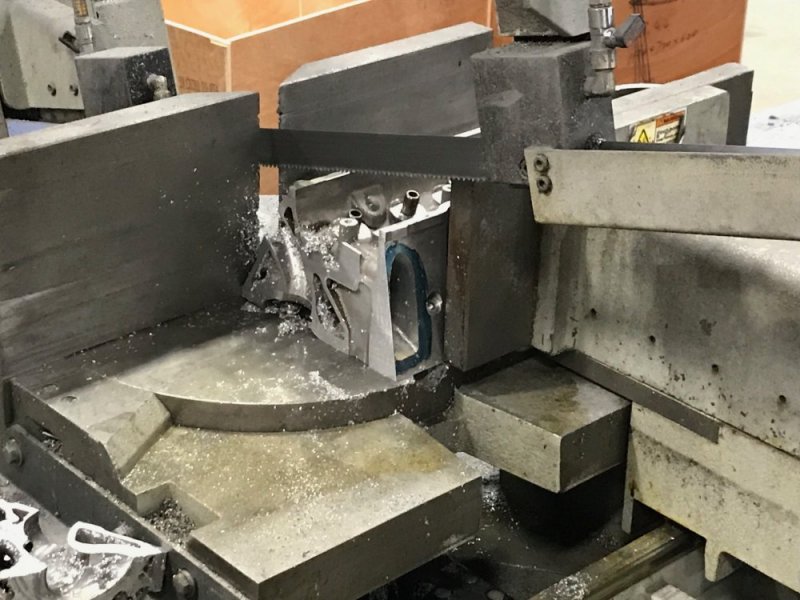
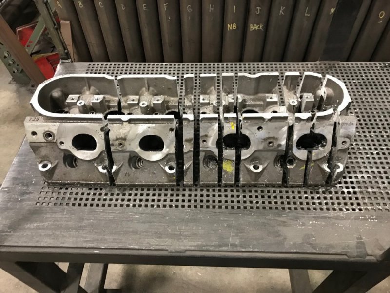
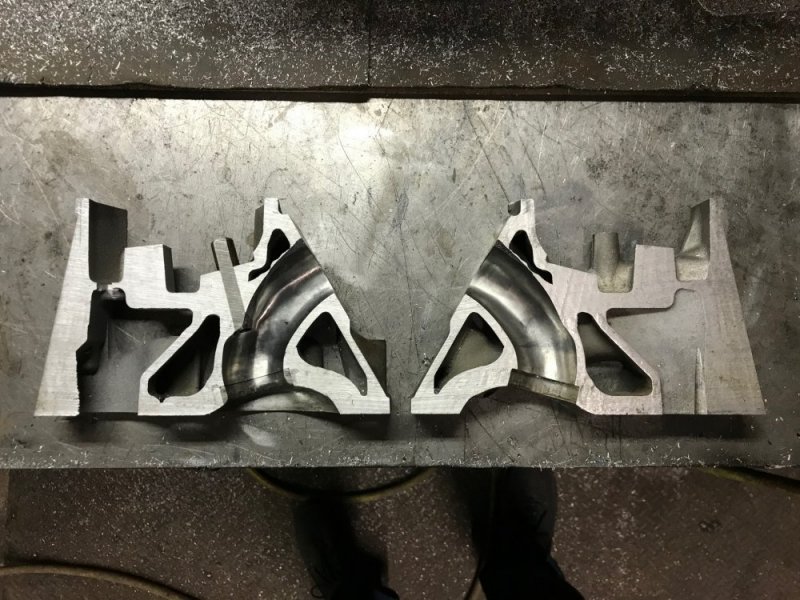
I decided that I should use my mistake as a learning experience. So I took one of the heads into work and hacked it up on the bandsaw.

56493

56492


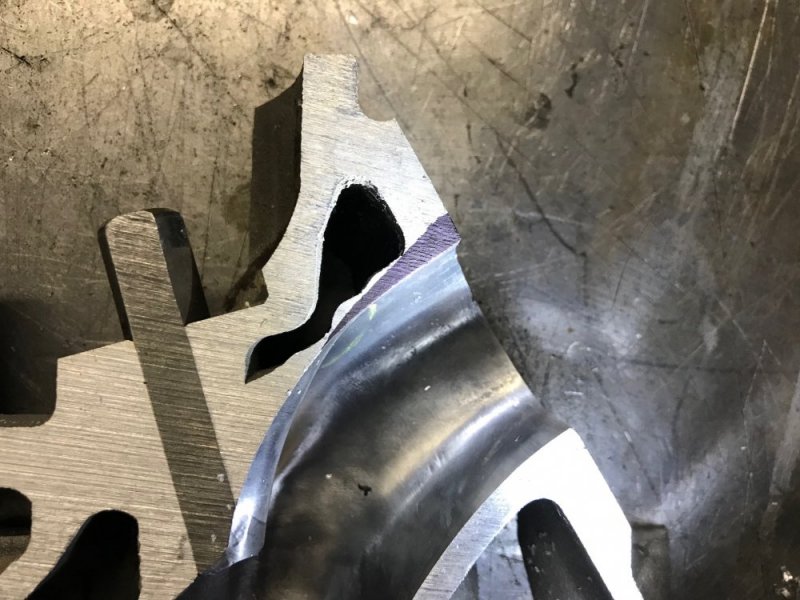
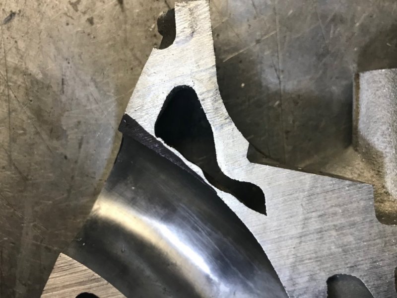
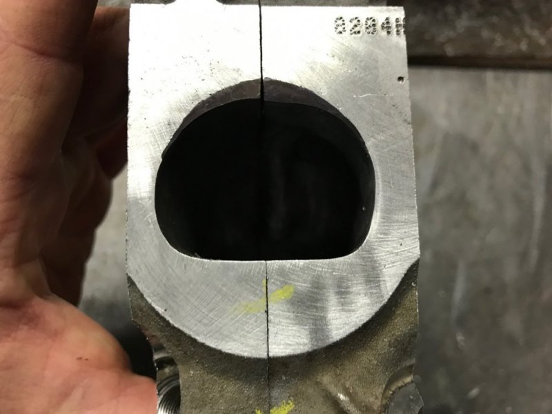
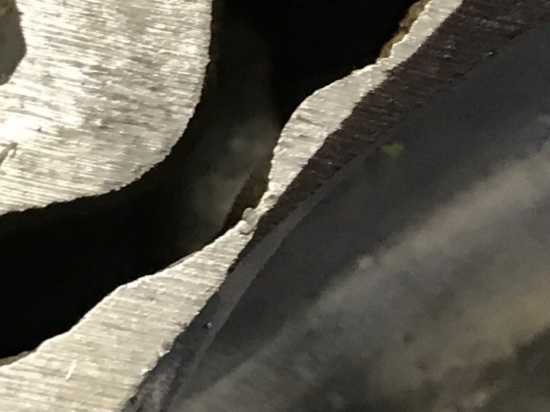
This way I could see exactly what material I had to work with. I haven't taken pictures of all of the slices yet, but I did take some of the critical exhaust port slices. Boy am I glad I started over! Even with the additional weld, the port wall is still really close to the coolant passage! The black marker on the casting approximates what the port was before filling it back in with weld - nearly paper-thin in spots!

564865648756488564895649056491
 
As of right now I have spent about 15 hours running the die grinder on the new set of heads. I have made some significant changes from the last set.

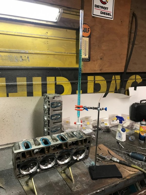
When I started the last set, I was planning on running a relatively small camshaft for this build. Because of that, I was interested in trying to make the swirl ramp really work for me at lower rpm. Who knows if what I did would have worked, but I felt like trying it. Well now I am going with a larger cam and felt like I should stick with a more proven design that really flows. Advanced Induction CNC ports LS heads that are a proven performer. So I found some decent pictures of the ports in their 226cc and 232cc heads that I could use for reference. I worked on one of the intake ports for a couple hours and decided to check the volume of the port to see if I was in the ballpark.
56498

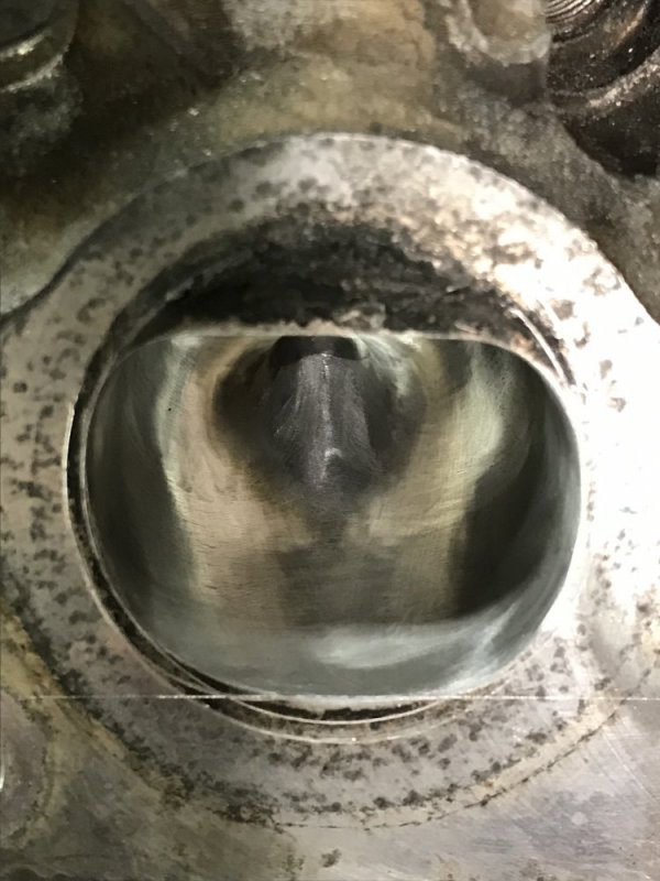
NOPE! I was only at 221cc! I couldn't believe it. And when they do their 226cc program, they don't even touch some parts in the port walls! So I was really missing something. I looked at the pictures some more and identified some areas I could probably port some more. A couple more hours of porting and now I was up to 225cc. Dang! That was where I ended Saturday. Sunday morning when I came back out to the barn I decided to look at my port and the pictures again with fresh eyes. I found 2 areas that looked different from the pics so I went to work there. This time I ended up with 228cc - good enough. To be clear - I know that volume is not necessarily an indicator of flow, I'm only using the volume measurement as a way to compare my work to their work. So I obviously haven't made all the changes that they have, but I'm hopefully at least in the ballpark. They probably remove more material from the short side radius, but I'm afraid of taking too much material off there and making it worse rather than better so I'm going to err on the side of caution. Here is what the finished intake port looks like:
56499565005650156502565035650456505


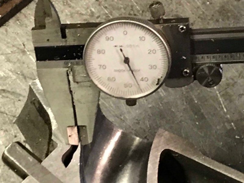
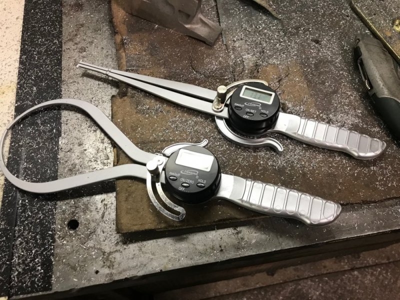
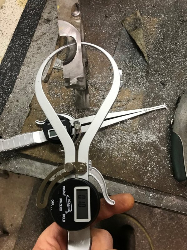
While working on the port it was SUPER handy having that cut up head. I referenced the casting many times to make sure I wasn't going to be getting it too thin in various locations. I bought a cheap set of outside and inside measuring calipers off of Amazon and they were really helpful in evaluating.
5649656497


Once I got the port to a point where I was happy I then started making the other 7 intake ports match. By then end of yesterday I was about 75% done. I was hoping to not have as much time invested in this set of heads by copying another design, but it turns out that copying was even more time consuming! Ah well, at least the work is turning out at a good quality and hopefully I find a decent amount of the flow that the AI heads have.
 
I wonder how accurately those passages are cast?
Hard to say. I didn't make cuts in the same locations on every port so I could do that level of comparison. And which is more variable - the casting or my grinding? I am using those calipers during the duplication process and it is really helping with my grinding consistency.
 
Keep in mind there is significant differences in some of the castings. I believe it was the 5.3l 706 castings that were prone to cracking so much so GM released a TSB for it. The 317 6.0l heads are supposed to be high flowing, but they have large chambers to lower the C/R, and you can't mill them much without getting into the cooling jackets(I believe they say .040 MAX). The 243's are supposed to be like 317's, but with smaller chambers.
 
I finished the last of the other 7 intake ports last night, so tonight was the start of the exhaust ports.

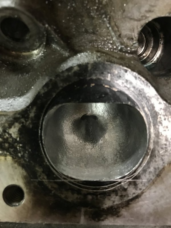
I decided to make a better outline for my port outlet. A few scribe lines with multiple circles got me a good and SAFE shape and size.

56539

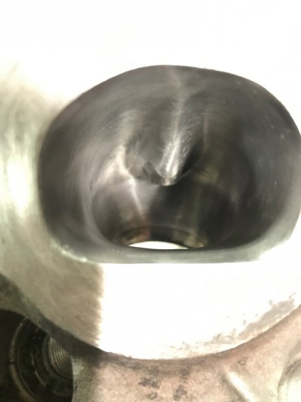
Then with pictures of the Advanced Induction ports as my guide I went after the first port with my burrs. I wasn’t sure if I’d finish one tonight or not, but the exhaust port is a lot simpler than the intake and took less time. I couldn’t find definitive exhaust port volume for the AI heads, but I did find a vague reference that made them appear to be 84cc, so that was my target. I ended up at 85.5, so I may have sacrificed a little velocity, but I am in the ballpark. They’ll probably be close to 86cc by the time I get done with the cartridge rolls and polishing and I think that’s fine.

56540565415654256543

Next up I’ll make the other 7 exhaust ports match this one and then it’s time to cartridge roll and polish the exhaust ports and combustion chambers. So far I have 24.5 hours into the heads so by the time I’m done this weekend I’m sure I’ll be close to 40 hours. Sheesh. BTW, I measured a stock exhaust port and it was right around 74cc, so I removed a fair amount of material on the exhaust port too.
 
Stuff I've read "old school" was not to polish the intake just the exhaust. Where's the fuel injected at on these engines?
Yep that still applies from what I’ve read. The fuel is injected in the intake port just before the port in the head. So you want the intake port rough to keep the air at the edges moving so the fuel stays in suspension. It is also supposed to increase the velocity of the air for the same reason a golf ball has dimples in it. I reckon those 2 things are related - the air is moving faster at the edge and therefore doesn’t stagnate so the fuel drops out, and bonus, the air is moving faster so more rams into the cylinder. I have read that the air works that way because intake air is subsonic. Exhaust air on the other hand is supersonic so it behaves differently. I guess that should be true, but I like the exhaust port to be shiny so carbon is less likely to stick to it. This is the same reason I like polishing the combustion chamber - keeping the carbon from sticking which could cause hot spots. Also knocking down any sharp edges that could become hot spots and cause preignition.
 
Back
Top