• Welcome to The Truck Stop! We see you haven't REGISTERED yet.

    Your truck knowledge is missing!
    • Registration is FREE , all we need is your birthday and email. (We don't share ANY data with ANYONE)
    • We have tons of knowledge here for your diesel truck!
    • Post your own topics and reply to existing threads to help others out!
    • NO ADS! The site is fully functional and ad free!
    CLICK HERE TO REGISTER!

    Problems registering? Click here to contact us!

    Already registered, but need a PASSWORD RESET? CLICK HERE TO RESET YOUR PASSWORD!

Running Too Much Boost, And Blew A Head Gasket.

bowtiebutler956

Active Member
Messages
581
Reaction score
207
Location
Harlingen, Texas
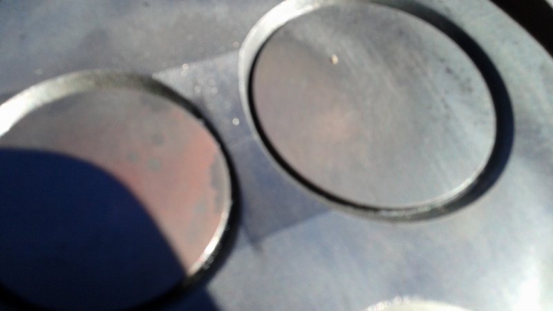
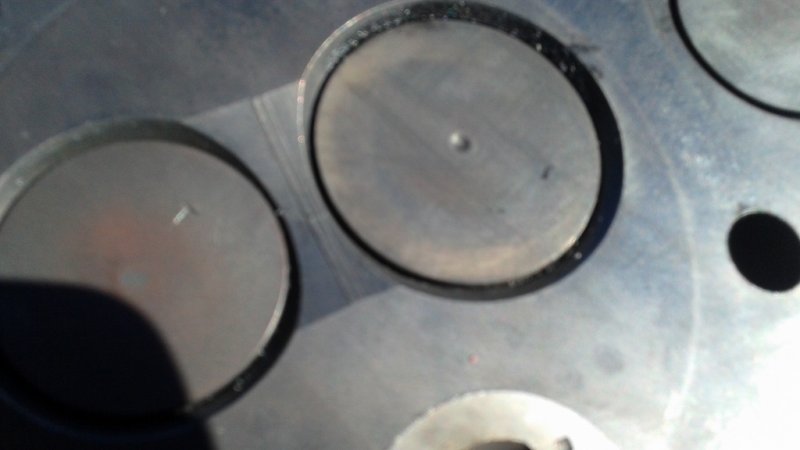
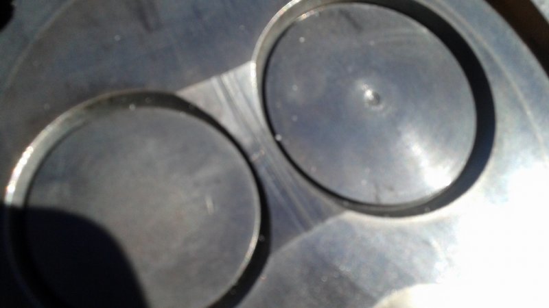
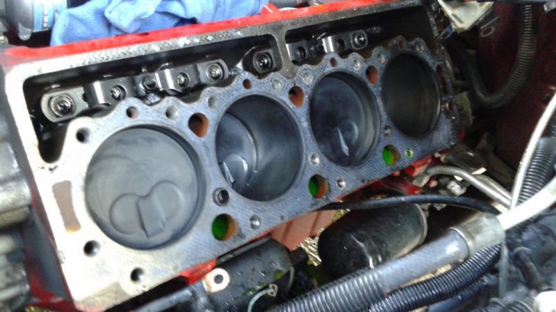
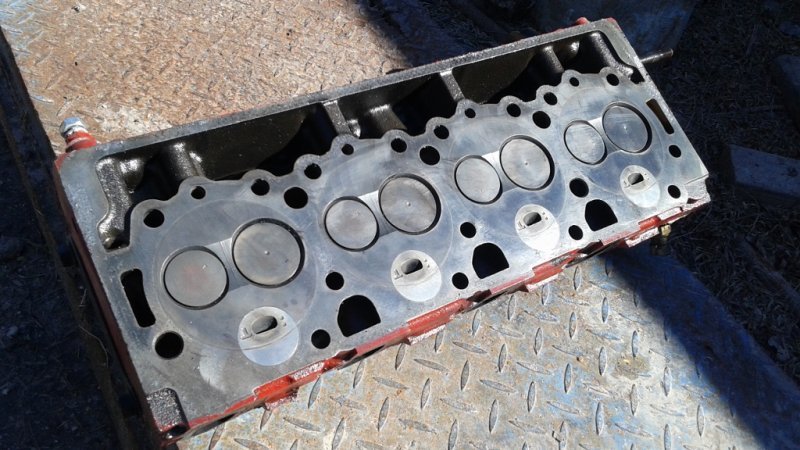
Well, I think the title says it all. I've been trying to dial in my new hopped up IP. I retarded the timing a little, turned up the fuel screw 1/4 turn, and was playing with different boost levels. I ran it a couple times at 30 psi peaks just to see if it made much difference. I didn't seem like it gained much that high, so I brought it down to a 25 psi peak. I had just finished making a WOT video, when I smelled coolant, but my temp gauge was still at 190. I'm now getting air in the cooling system! Not just a little either, a lot! :mad: I knew this might happen as I'm still running TTY bolts, but its still a bummer. I was getting ready to buy a new set of 285 75 16 tires for it, but not anymore. I really wanted those tires. :(:D So, it will be getting ARP studs, and Felpro +.010 gaskets. Hopefully the heads are still usable.
When my videos finish uploading to youtube, I'll post them. It didn't pick up alot more power, but it seems to have shaved almost a second off of my 0-80, before I started smelling coolant.
Matt
 
I'd say 18 psi is good w/20 psi spike that's were I'm staying w/my boost, ARP and perhaps solid copper gaskets "if they can be had are best route." I don't remember your turbine cm is it small or, think back pressure played a role or?
 
Wow. A whole second off 0-80 is a lot! But sorry to hear about the head gaskets. Hopefully that's all it is. Can wait to see it up and running again. You definitely have one of the quickest 6.5L around.... when the heads stay where they should. Hopefully your not too mad, when I break something because of too much power I am always just a bit proud of myself to go along with the disappointment of breaking.
 
Dang! I hate when that happens, fingers crossed for you.
Thats what I said, and I'm hoping for the best, but trying to mentally prepair myself for the worst.
I'd say 18 psi is good w/20 psi spike that's were I'm staying w/my boost, ARP and perhaps solid copper gaskets "if they can be had are best route." I don't remember your turbine cm is it small or, think back pressure played a role or?
My turbo is supposed to have a 14cm housing, but who knows. I did a video of my drive pressure awhile back, and posted it in my turbo thread, but I'll post it here as well. In the test, the highest drive pressure was 1.5 to 1, but that was up to a little past 20 boost at WOT. I didn't take any readings at 30, so its hard to say how efficient the turbo is at boost levels that high. Most of the time the drive pressure was in the 1:1 to 1.2:1 range, but made it to 1.5:1 at high RMP WOT over 20 on the boost. Here is the vid,

Wow. A whole second off 0-80 is a lot! But sorry to hear about the head gaskets. Hopefully that's all it is. Can wait to see it up and running again. You definitely have one of the quickest 6.5L around.... when the heads stay where they should. Hopefully your not too mad, when I break something because of too much power I am always just a bit proud of myself to go along with the disappointment of breaking.

While I'm proud of the way my 6.5 runs, I can't say I'm proud of breaking parts.:eek:

Matt
 
Bummer! Keep us posted. :(

Thanks Nate, and I will.

I started the teardown today. Pulled both exhaust manifold, and the intake. Here is a pic of today.

Matt
 

Attachments

  • 20150126_151832 (1024x576).jpg
    20150126_151832 (1024x576).jpg
    84.1 KB · Views: 23
  • 20150126_151823 (1024x576).jpg
    20150126_151823 (1024x576).jpg
    83.5 KB · Views: 22
  • 20150126_151851 (1024x576).jpg
    20150126_151851 (1024x576).jpg
    65.5 KB · Views: 22
That sucks so bad, I'm so sorry! :oops: I'll be interested to hear how hard it is to get that Goop or whatever that stuff was that you used apart.
 
That sucks so bad, I'm so sorry! :oops: I'll be interested to hear how hard it is to get that Goop or whatever that stuff was that you used apart.
You mean the stuff I just used on the drivers side valve cover? No doubt, I'll be having to straighten out the edges of my valve covers from all the bending thats going to be required to get them off! :rolleyes: I was really happy with that repair, as it was nice, and dry! Oh well, I'll let you know how difficult it is. :D

Matt
 
Please do. I want to make sure I use good stuff to put mine together. I don't know what GEP used to put that thing together but it was super tough to get apart!! Lots of tin straightening to do. :( It will be nice to compare to the Ultra Black I used this past summer to put the old engine together.
 
I've been suspect of anything aside a short spike over 20 psi because of the potential of the 3" downpipe becoming the choke point on a V8 at higher pressure ratios, maybe just over thinking here.
 
Last edited:
Looking at your HX40w ii thread and I see what looks to be a "10" stamped inside the turbine inlet where you ported it "this number and its location indicates the turbine cm 2."
 
Last edited:
Being that it is a CKO it's hard to say exactly what cm the turbine is the difference on t3 mounting is in the turbine twin scroll inlet larger cm have dimples in all four corners so mounting bolts an clear the turbine housing the larger t4 lacks these dimples, I see your turbine has dimples on the gate side only suspect the only way to tell size is have others post images of their turbine inlets for comparison.
 
Being that it is a CKO it's hard to say exactly what cm the turbine is the difference on t3 mounting is in the turbine twin scroll inlet larger cm have dimples in all four corners so mounting bolts an clear the turbine housing the larger t4 lacks these dimples, I see your turbine has dimples on the gate side only suspect the only way to tell size is have others post images of their turbine inlets for comparison.

Yes, my housing did have a 10 stamped on it, but I own an HX35W with a 12cm housing, and my 40WII's turbine housing is every bit as big, and bigger on some of its demensions. Like you said though, its very hard to say with the CKO's. The HX35W is what I took the compressor side off of, and installed on my 40WII, because it had a larger 56mm inducer on it.

Matt
 
Alright, the engine is apart. Each head has gained another crack. One of these heads is the original 1993 head that came with the truck. Its the one that had a half length crack when I installed it, and its no gained another half length crack. Its strange, this 93 head has a ridge in the casting between the valves, that seems to stop cracks at the halfway point, not allowing them to go all the way between the valves.
The other head is from a 1996 engine that I installed on this one. It had one full length crack between the valves which has gotten worse, and can now be felt with my nail. It has gained another very fine crack that I can see, but not feel.
Both of these heads cracks were on the back cylinder when I went threw the engine awhile back, so I rotated the heads around, so that the cracks would be on the cooler running front cylinders, but they have both gained a crack on the back cylinders again, so now all 4 ends have cracks, rather than just two. I guess that wasn't a very bright idea. :rolleyes:
The right side head gasket was badly blown towards the front, and I'm actually surprised it wasn't getting coolant in the cylinder when the engine was off. I forgot to take a picture of the gasket, but I will tomorrow.

On the up side, my cylinders look fantastic
I haven't pulled the valves yet to see if the cracks go threw the seats yet, but I will tomorrow.
Each picture below is a different crack. The first pic is the worst one, and the next pic is the new crack in the same head.
The next two pics are of the 1/2 length cracks in the other head, and I think you should be able to see the ridge in the head casting that stops the crack from going all the way across.
I took these pics with my phone, so they're a little blurry.

Matt
 

Attachments

  • 20150127_150456 (1024x576).jpg
    20150127_150456 (1024x576).jpg
    36.2 KB · Views: 19
  • 20150127_150528 (1024x576).jpg
    20150127_150528 (1024x576).jpg
    33.7 KB · Views: 18
  • 20150127_150547 (1024x576).jpg
    20150127_150547 (1024x576).jpg
    35.5 KB · Views: 18
  • 20150127_150608 (1024x576).jpg
    20150127_150608 (1024x576).jpg
    35.6 KB · Views: 18
  • 20150127_153622 (1024x576).jpg
    20150127_153622 (1024x576).jpg
    69.7 KB · Views: 18
  • 20150127_150538 (1024x576).jpg
    20150127_150538 (1024x576).jpg
    87.8 KB · Views: 18
Please do. I want to make sure I use good stuff to put mine together. I don't know what GEP used to put that thing together but it was super tough to get apart!! Lots of tin straightening to do. :( It will be nice to compare to the Ultra Black I used this past summer to put the old engine together.

Nate, I would say the sealant I used here recently (permatex The Right Stuff) is more like the stuff that came on your GEP. Originally I used Mega Black to seal my valve covers, and oil pan, but the drivers side valve cover started leaking, and I was told the Right Stuff works much better on our diesels. Removing both the valve covers today, the one that I used the mega black came off hard, but the one I used the Right Stuff on was ridiculously stuck on there. Something else I noticed. Both times I removed the valve covers with the mega black, the silicon stayed mostly on the head, where the Right Stuff stayed almost completely on the valve cover. Here are a couple pics.
The cover thats black on the inside has mega black, the one thats raw metal has the Right Stuff.
Matt
 

Attachments

  • 20150127_154357 (1024x576).jpg
    20150127_154357 (1024x576).jpg
    64.5 KB · Views: 11
  • 20150127_154404 (1024x576).jpg
    20150127_154404 (1024x576).jpg
    47.5 KB · Views: 11
Nate, I would say the sealant I used here recently (permatex The Right Stuff) is more like the stuff that came on your GEP. Originally I used Mega Black to seal my valve covers, and oil pan, but the drivers side valve cover started leaking, and I was told the Right Stuff works much better on our diesels. Removing both the valve covers today, the one that I used the mega black came off hard, but the one I used the Right Stuff on was ridiculously stuck on there. Something else I noticed. Both times I removed the valve covers with the mega black, the silicon stayed mostly on the head, where the Right Stuff stayed almost completely on the valve cover. Here are a couple pics.
The cover thats black on the inside has mega black, the one thats raw metal has the Right Stuff.
Matt

Thanks for the feedback! Gonna have to find that stuff.
 
Yes, my housing did have a 10 stamped on it, but I own an HX35W with a 12cm housing, and my 40WII's turbine housing is every bit as big, and bigger on some of its demensions. Like you said though, its very hard to say with the CKO's. The HX35W is what I took the compressor side off of, and installed on my 40WII, because it had a larger 56mm inducer on it.

Matt
Perhaps, it is too small for your application and your stuck with tall gears so you can't go big w/o spool valve.

I did lots of research before I jumped and the one I bought actually did cross ref to the Holset Super 40 but with an 18 cm2 instead of a 16 cm2.
 
Back
Top