• Welcome to The Truck Stop! We see you haven't REGISTERED yet.

    Your truck knowledge is missing!
    • Registration is FREE , all we need is your birthday and email. (We don't share ANY data with ANYONE)
    • We have tons of knowledge here for your diesel truck!
    • Post your own topics and reply to existing threads to help others out!
    • NO ADS! The site is fully functional and ad free!
    CLICK HERE TO REGISTER!

    Problems registering? Click here to contact us!

    Already registered, but need a PASSWORD RESET? CLICK HERE TO RESET YOUR PASSWORD!

IDI tecchie info courtesy of Great White

great white

Well-Known Member
Messages
4,007
Reaction score
109
Location
Canada's Ocean Playground
Just posting for my own future reference.

The Indirect Injection Engine (IDI)

A later development was the IDI engine that utilises a separate combustion chamber, connected to the engine cylinder, into which the fuel is injected and combustion is initiated.

A heat resistant insert with low heat conductivity is located within the combustion chamber so it quickly heats up and retains heat from combustion, providing extra heat to enable quicker ignition. The fuel is injected into the hot combustion chamber as a jet at a low pressure compared to the fine high-pressure spray of a DI engine. The fuel jet hits the hot insert where ignition is initiated; the fuel is distributed around the combustion chamber as combustion continues. The expanding burning fuel, along with partially burnt and unburnt fuel, is carried into the hot engine cylinder where further oxygen is available and combustion continues.

The most common prechamber format utilised is the Ricardo Comet design developed by Ricardo and Company of Shoreham, Sussex, UK. With this design air is pushed from the cylinder into a circular ‘swirl chamber’ through a tangentially aligned throat. The bottom half of the chamber along with the throat is constructed from a nimonic alloy designed to maintain high temperatures during engine operation. The temperature of the compressed air is raised further while passing through the throat. A vigorous swirl motion is initiated as the air is forced into the circular swirl chamber. The fuel is injected into the swirl chamber and rapidly atomised within the mass of hot turbulent air.
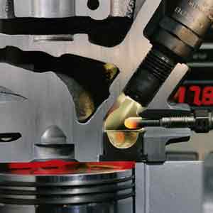
IDIphoto.jpg


Photo:Bosch
IDI engine – Picture shows fuel being injected into a swirl chamber with a heated glow plug – not shown is the throat from the engine cylinder to the swirl chamber - Note the lower half of the chamber constructed from nimonic alloy.

Mercedes IDI engines utilised a different design in which a jet of fuel is fired at a ball like baffle surface. The jet is broken by the baffle surface and distributed around the prechamber being finely dispersed by the turbulent air charge. Upon combustion the fuel/air mixture is carried through several bores into the main engine cylinder. Mercedes later improved this design, reshaping the prechamber, creating a swirling air motion to improve combustion.

The advantage of IDI engines is that they can operate at higher engine speeds as the more efficient fuel and air mixing provides faster combustion. Cars and small commercial vehicles require a small, light engine which must be able to operate at higher speeds to provide the necessary power, with the advent of the IDI engine the use of diesel engines in such vehicles became widespread.

The heat lost due to the increased surface areas of the combustion chamber and the pressure drop between cylinder and combustion chamber make it necessary for the engines to operate at higher compression ratios to provide enough heat for ignition. The lost heat and force required to push the air into the combustion chamber is wasted energy making IDI engines around 10-15% less efficient than DI units.

IDI engines became the engine of choice in small vehicle applications as a small engine could produce more power at higher speed providing a suitable power/weight ratio for such applications. Recent advances in fuel injection technology, which provide more precise fuel delivery, allow faster combustion within a DI engine. The improved efficiency of the DI cycle has spurred the fitment of such engines to become more common in small vehicles.
 
just another post to capture some info:

IDI engines are fueled by self-cleaning, single-hole, pintle-type nozzles. The combustion process is too complex to be explained here, but my above-mentioned SAE technical paper No. 960058 describes it in more detail. In general, it is a two-step combustion process characterized by its speed and tolerance of fuel-system inconsistencies that allows operation of present automotive engines (such as the Mercedes IDI engine mentioned above) up to 5000 rpm. Combustion is faster and more complete than with DI systems, with more of the fuel being consumed even with lower amounts of air per cycle (lower A/F ratio) at the same smoke level. Since no swirl is required in the main chamber, high-efficiency directed intake ports can be used instead of the helical ports employed by DI engines, and more air is processed to provide higher volumetric efficiency with smoke-limited A/F ratios of less than 20:1. The combination of higher volumetric efficiency, reduced port-pumping losses, higher engine speed and higher combustion efficiency at lower A/F ratios produce higher power; typically, 10-15% more power at the shaft for similar-displacement engines. The indicated cylinder power is even higher, but two factors contribute to high thermal losses, which are detrimental to power output and fuel consumption. The first is the pumping losses in and out of the pre-combustion chamber and the second is the heat losses through the pre-combustion chamber walls. The technical world has concluded that these problems are unsolvable for small engines, and interest in pre-combustion chamber combustion has been lost, in spite of the fact that the overwhelming majority of pre-combustion chamber combustion characteristics are, for small passenger cars, far superior to those of the DI system. The Ricardo side pre-combustion chamber has remained unchallenged, except by some modifications that other researchers have performed including some work that I have done, as described in my U.S. Pat. No. 5,417,189, issued May 23, 1995 and my aforementioned SAE technical paper No. 960058. The only new application of a pre-combustion chamber system combined with four valves can be found in the new Mercedes-Benz DOHC family. Even so, the pre-combustion chamber and injector tip in this DOHC family differ very little from the 1927 Mercedes-Benz designs. Therefore, to continue enjoying all the benefits of pre-combustion chamber engines, while improving the fuel consumption profile, it is important, amongst other measures, to minimize the two main sources of losses; that is, pumping and thermal as exhibited by the current Ricardo and Mercedes designs. In reality, it is not required that they be eliminated completely. The reason being, as already explained, that the energy released by combustion is far higher than that of the DI system due to the more efficient burn. Therefore, the IDI system can tolerate some losses and still be competitive with DI; however, both sources of heavy losses must be reduced.


Other four-cycle, four-valve American engines from Cooper Energy Services, as well as from Caterpillar and Waukesha have also used pre-combustion chambers for many years, some as pure IDI diesels; others as spark-ignited gas engines. The latter are very popular in environments where low emissions are already closely regulated. With the trend towards the use of pre-combustion chambers, it has been predicted that newer, more efficient pre-combustion chamber designs will be required to minimize the pre-combustion chamber heat losses through heat transfer.

The need to keep the pre-combustion chamber as hot as possible has been acknowledged from the earliest use of the Ricardo "Comet" pre-combustion chamber in 1929. In the "Comet" pre-combustion chamber, the lower inserted portion of the pre-combustion chamber, called the "cup", is made of exotic heat-resistant material such as Nimonic and is designed to maintain an insulating air gap between its sidewalls and the cavity bored inside the head so as to reduce the heat losses. However, with the "Comet" pre-combustion chamber, the upper cavity is typically machined in the structure of the cylinder head and is prone to crack because of the high thermal gradient between the hot inside of the pre-combustion chamber walls and the cooler outside walls exposed to the cooling media compounded by the rates of firing pressure and maximum firing pressures as the fuel is ignited. To avoid this problem the design uses a water jet, typically drilled across the head, between the two valve ports (these engines typically being two-valve engines), both to cool the bridge between the valves and to impinge on the pre-combustion chamber's upper cavity. The upper-half of the pre-combustion chamber, therefore, not only suffers from the normal heat losses through its walls made of parent material exposed to the cooling jacket, but also has to cope with water being impinged upon it to avoid cracking the wall. In the process, it loses a very considerable amount of heat energy.

Some engines, made by Isuzu and others in Japan over fifteen years ago, upgraded the material of the pre-combustion chamber "cup" from Nimonic to ceramics, which has a far lower heat transfer coefficient; however, the top half of the pre-combustion chamber was not changed and still suffered high heat losses. Developments under my direction, using the lower pre-combustion chamber cup from Isuzu engines on an experimental Chrysler engine, proved that the engine not only reduced its fuel consumption by 4-5%, started faster, and produced less noise, but that it also burned faster and cleaner, allowing the injection timing to be retarded for reduced NO.sub.x, as well as hydrocarbons, particulates and smoke. Recognizing the fact that the main losses were still through the upper-half of the pre-combustion chamber ; a heat shield designed for disposition inside the upper pre-combustion chamber cavity. The heat shield is intended to minimize the high heat losses of the pre-combustion chamber at this location by increasing the total wall thickness and creating an insulating air gap between the shield and the parent-metal cavity. It has been calculated that such shield could improve the engine's fuel consumption another 7-8 percent and all the other combustion parameters as well, by reducing the heat losses.
 
just another (grab a coffee if you plan to read it):

In the late 1920's, divided chamber combustion systems for two-valve type cylinder heads opened the way for small high-speed diesel engines with designs by Harry Ricardo, and Mercedes-Benz. Many forms of divided chamber combustion systems have been proposed, but the two forms identified above are still the main designs for current diesel engines. The Ricardo design has since been applied to overhead valve (OHV) cylinder heads and to overhead camshaft (OHC) cylinder heads. Recently, some newer engines have been introduced with OHC and three valves per cylinder (two intakes and one exhaust). The basic design of the Ricardo "Comet" Mk Vb pre-combustion system (also often referred to as "swirl chamber" system) used on these engines, however, remains essentially the same as the original 1939 version. A minor change has emerged in recent Japanese engines consisting in the reversal of the relative positions of the fuel injector and the glow plug to eliminate air flow interference within the precombustion chamber otherwise caused by the glow plug.

While the "Comet" system provided excellent performance when first introduced, under present, more demanding operating conditions, it has many thermodynamic problems. One problem is that combustion does not actually take place as originally understood. The original perception was that a secondary combustion process took place in the dual pocket combustion cavity ("swirl pockets") formed in the main combustion chamber under high swirl conditions. The present thinking is that this was not accurate. In order to understand why the original perception is untrue, one needs to analyze the whole combustion process and the thermodynamic conditions immediately proceeding combustion. Following is such an analysis.

During engine operation, as the piston moves upwards towards the top-dead-center (TDC) position at the end of the compression stroke, air in the reduced cylinder volume moves towards the precombustion chamber and the area in the combustion chamber occupied by the "swirl pockets" through a well known squish process in which air is literally squeezed between closely spaced portions of the piston surface and the fire-deck surface of the cylinder head. Since the above identified "swirl pockets" (or main combustion volumes) were located to one side of the piston, a relatively large squish area was created over the remaining flat piston top from which air discharge was required. The air is discharged from the squish area by pumping energy delivered by the piston. The pumping energy is dissipated in air turbulence and friction as the air moves through the ever decreasing volume defining the squish clearance space between the piston and the cylinder head's fire-deck surface. Resultantly, energy in the form of heat is transferred to the piston through its top surface as well as to the cylinder head through its fire-deck surface. All of this heat energy is wasteful and must be subsequently absorbed by the engine oil and coolant. Finally, the heat energy must be disposed of through the cooling system which uses up additional energy by being required to drive the water pump and the radiator fan.

As can be understood, wasted pumping energy decreases the energy of the compressed air in the combustion chamber thereby lowering its compression pressure and temperature. Although this is detrimental under all engine running conditions, it is most wasteful during cold cranking and cold engine operation because the top piston surface and lower cylinder head deck surface are cold and thus absorb a maximum quantity of energy from the air moving from the squish areas. A high temperature differential between the surfaces and the air generates energy losses and, as is well known, whatever energy is lost must be compensated for by increasing the nominal or design compression ratio of the engine so as to reach the proper compression temperature for auto-ignition of the fuel in the combustion chamber. This, apart from being very expensive from the manufacturing standpoint, forces the engine to operate when hot at a compression ratio higher than needed for ignition and produces a combustion resulting in an increase in the firing pressure and the friction of the moving components of the engine, which must be made correspondingly stronger, and heavier. The higher firing pressure also requires a stronger engine structure which increases the vehicle's weight and fuel consumption. Moreover, the increased friction increases the fuel consumption and emissions as well as engine wear.

In addition, pumping air during the compression process from the squish areas between the cylinder and top surface of the piston and into the swirl pockets formed in the piston creates turbulence or swirl in these pockets. Such swirl is desirable in gasoline and direct injection diesel engines because it occurs before TDC and serves to accelerate combustion. However, in an indirect (divided chamber type) engine, it is of no benefit because combustion initially takes place before TDC in the pre-combustion chamber which has its own separate swirl-generating mechanism. Thus, by the time burning gases are discharged from the pre-combustion chamber into the main combustion chamber, the piston is already past TDC when previously created squish activity is past. Also, this divided chamber type of engine accelerates the secondary combustion process in the main combustion chamber by the kinetic energy of the products of prechamber combustion which exit through the transfer passages and by the highly reactive unburned fuel and the temperature of the burning mass. Accordingly, it is a waste to expend energy in creating swirl or turbulence.

Research has indicated that pumping work is substantially reduced if the area of combustion in the main combustion chamber (previously referred to as "swirl pockets") is expanded and centrally positioned so that any air that must be moved from the now volumetrically reduced and better-distributed smaller squish areas travels a minimum distance to the centrally located pockets. Although some air movement must always occur, the proportion of air movement from the squish areas is minimized and resultantly the energy expended is minimized.

The actual combustion process in the "Comet" systems begins in the pre-combustion chamber when fuel is introduced. The interior of the chamber is highly turbulent and confines a hot mass of air within hot pre-combustion chamber walls. Inasmuch as all of the fuel is introduced in

the pre-combustion chamber and such chamber holds only a small portion of the total combustion air mass, the air-fuel (A/F) ratio within the pre-combustion chamber can be very rich, particularly under high load operation. Therefore, only a portion of this fuel burns with the air at a roughly stoichiometric A/F ratio. The rest of the fuel, which is heated and well mixed with the air and already formed products of combustion dissociates into highly reactive radicals. As the burning mass is expelled from the pre-combustion chamber, secondary combustion begins in the main combustion chamber. It was previously thought that this secondary combustion process occurred between the products of prechamber combustion and the fresh air in the piston swirl pockets, at a higher level of swirl, beginning from about five degrees ATDC and continuing for forty-five to fifty degrees of crankshaft rotation after TDC. However, research confirms that this is not very accurate. In reality, as the discharge from the pre-combustion chamber enters the piston pockets after TDC, the piston is rapidly descending during an expansion stroke and any air originally in these swirl pockets migrates to the ever increasing clearance volume being created over the large piston squash area between the top of the piston and the cylinder head's fire-deck; area which had little air when the piston was at TDC due to the minimum clearance.

A single, centrally located and relatively small transfer passage from the prechamber discharges its products of combustion as a relatively high-velocity torch and by a considerable expenditure of energy (pumping work). There is little incentive for the discharge to enter the piston's swirl pockets because the kinetic energy and momentum of the burning mass is too great to effect a change in direction and there is no other force to cause it to change direction. Specifically, the splitter formed on the piston top between the downstream circular ends of the "swirl pockets", intended to redirect the torch to enter the swirl pockets and burn therein while swirling, has descended with downwards movement of the piston and thus is no longer effective for changing the flow direction from the prechamber's transfer passage. Accordingly, secondary combustion continues past the pockets along the transversal centerline of the cylinder and follows the mass of air which has migrated to the far side of the chamber. This creates very high temperatures and very high levels of heat transfer to the piston because of the energy level and agitation of the combustion products. As a result, along a transversal line running between the valve bridge, the center of the piston's upper surface, and a portion of the exhaust valve seat a very high thermal loading is applied which could result in piston failure at the base of the splitter, as well as valve failure. Controlling these conditions and inhibiting valve failure requires the use of expensive materials.

The above thermal load problems have been more pronounced since engines began to be turbo-charged as indicated in a technical article written by J. A. Stephenson entitled "High Speed Diesels", appearing on page 245 in the 1988 issue of "Automotive Technology International". Moreover, confirmation of the above analysis can be found in the book entitled "Internal Combustion Engine Fundamentals" published by McGraw Hill Publishing Company (1988), and authored by J. B. Heywood. FIGS. 10-4 on page 499 of this book were supplied by Ricardo and Co. to Professor Heywood of the Massachusetts Institute of Technology and show in color pictures a sequential series of combustion phases. By following the flame propagation in the pictures from prechamber through combustion in the main chamber, the pictures confirm that the true development of the combustion process occurs transversely downstream of the piston's center and not in the swirl pockets.

Another characteristic of engines using the "Comet" pre-combustion system is that they require very tight clearances between the piston top and the fire-deck and valves. This is necessary to avoid squandering of the chamber's clearance volumes and reducing the compression ratio. These engines already require very high compression ratios which are difficult to achieve and control during production. The need for high compression ratios is due to the fact that the surface area of the pre-combustion chamber volumes also lose a great amount of heat to the engine coolant. When that energy loss is added to the pumping losses by high velocity passage of gases through the transfer port during the compression stroke, plus the wasted squish energy and heat transfer from it, the total detracts from the potential pressure and temperature at the time of injection and increases a delay in fuel ignition. Of course, this problem is worse during cold-start cranking and operation when much of the heat of compression is lost to the cold surfaces forming the combustion chamber and the prechamber walls. To avoid a resultant compression temperature too low to start the engine, the nominal or design compression ratio (NCR) was typically increased to a level unnecessary for normal operation. This requires a judicious control of clearance volumes in the main combustion chamber where only so much space can be allocated to the squish area. The problem then becomes a "chicken and egg" situation because the high NCR and resulting low main combustion chamber clearance volumes force a tight mechanical clearance between the piston and the lower deck of the cylinder head and between the piston and the valve heads.

In some prior engines, the clearance may be less that 0.001 or 0.002 inch under hot running conditions. This clearance would be just enough so that the piston and the valves do not contact during the valve overlap period of the cycle. Also, the valve lift is decreased during the overlap period occurring near TDC at the beginning of the intake period. The minimized valve lift causes unnatural valve timing events not seen in other type of engines. Specifically, the Intake Valve Opening (IVO) is forced to occur at a later than thermodynamically acceptable place in the cycle. Also, the Exhaust Valve Closing (EVC) is designed earlier than thermodynamically acceptable in the cycle. The resultant short overlap duration and minimum valve lift produces poor air and exhaust flows which has dire thermodynamic consequences. Thus, recompression spikes can occur under high-load, high-speed conditions as the exhaust valve is almost or totally closed while the intake valve is not open enough causing exhaust gases to be trapped in the combustion chamber with no place to go as the piston approaches TDC. The resultant recompression is undesirable as it produces negative work or in other words extracts energy from the piston. This will limit the engine's power and high speed potential and increase fuel consumption, smoke, noise, and emissions. Worse yet, the recompressed gas typically expands back into the intake manifold when the intake valve is opened. Resultantly, the exhaust gas heats the intake valve, the intake port, and the intake manifold. This heating reduces the volumetric efficiency of the engine and the EGR-like effect under high-speed, high-load conditions is not a welcome addition to the cylinder charge. Since the exhaust re-ingested into the cylinder takes the place of clean air, it also further reduces the volumetric efficiency and is the main cause of increased smoke and reduced power output. Also, the smoke carries highly abrasive carbon particles to erode pistons and piston rings. Further the particles are carried into the lubricating oil, thus forcing frequent oil changes. The exhaust re-ingestion also increases the fuel consumption, emissions, and the cylinder's thermal loading. The hot recompressed exhaust gas also transfers heat energy to the bridge between the valves and to the piston and further increases their thermal loading.

The abnormal timing schedule begets later than thermodynamically correct Intake Valve Closing (IVC), especially as two-valve engines require high valve lift and duration. Earlier than thermodynamically correct Exhaust Valve Opening (EVO), which occurs for the same reasons, not only wastes expansion energy which otherwise would contribute to engine power but instead becomes wasted pumping energy, as exhaust products in the exhaust system which is overloaded by such higher-energy exhausts products, must be mechanically evacuated by piston movement. Power output and mechanical efficiency are reduced. Fuel consumption, emissions, smoke, exhaust temperature, and thermal loading on combustion chamber components are increased.

In all of these prior swirl type, divided chamber engines, the main response to the problem of cracked bridge portions between the valves consists of drilling holes, one per cylinder, transversely through the metal of the lower deck of the cylinder head. The holes start opposite the location of the pre-combustion chamber and run through the bridge and discharge in front of the cast boss for the pre-combustion chamber. The sole purpose of these holes is to cool the bridge and exhaust valves. The approach is expensive because, apart from the drilling process itself, it also requires a cast boss and extra metal in the lower deck of the cylinder head. Each hole must be of relatively large diameter to avoid the risk of a broken drill bit and high cylinder head scrappage rates. The transversal hole must be plugged on the outside to avoid coolant leakage and must register with another vertical passage reaching through the cylinder head gasket and the top deck of the engine block into the block's water jacket. The metal boss at the bridge's center must be thick enough to run the drill causing kinks or bulges to exist in the intake and exhaust ports that reduce the port's flow coefficients. The worst result is that the thickened (actually widened) drill boss over the bridge will typically force the valves to be smaller than otherwise possible. The smaller valves reduce the engine's air flow capacity and the power associated with it. Thermodynamically, the long passage also forces unnecessary cooling of the fire deck and, with its discharge right in front of the pre-combustion chamber, induces additional heat losses from it. These losses also increase the cooling system loads which then require a larger water pump and radiator for increased parasitic losses and extra manufacturing cost.

Applicant's U.S. Pat. No. 5,309,879 issued on May 10, 1994; U.S. Pat. No. 5,392,744 issued on Feb. 28, 1995; and U.S. Pat. No. 5,417,189 issued on May 23, 1995 disclose solutions to correct the above described valve event problems and allow design of the engines with a lower NCR and provide better start-ability and low speed operation. A solution to the basic thermodynamic problem is provided by eliminating the swirl pockets of the original Comet engines and creating a dual pre-combustion chamber associated with dual valve-relief pockets in the piston. These valve-relief pockets serve to provide valve clearance for valve opening at a partial lift position during the overlap period of the engine cycle. They also permit desirable valve timing events. The valve overlap period is desirably increased by an earlier IVO and later EVC so as: to eliminate the possibility of recompression spikes; to allow proper scavenging of the products of previous combustion; to improve the ability to fill the chamber with clean air; and to reduce thermal loading of the combustion chamber. Thus, by advancing the IVO and retarding the EVC, it is also possible to desirably advance the IVC and retard the EVO. The earlier IVC produces higher compression pressures during cranking and better start-ability. The thermodynamic improvement results in an increase in the effective compression ratio and increased trapped volumetric efficiency resulting from less blow-back of air from the cylinder into the intake manifold during the early stages of the compression cycle. The later EVO extracts more energy from the combustion gases and expels a mass of lower energy exhaust during the exhaust process. It also lowers the energy expenditure in carrying out the exhaust process; which reduces fuel consumption, emissions, and thermal loading.

The above identified patents also offer solutions for reducing high thermal loading on the valve bridge and on the top of the piston. For example, the '744 patent discloses a four valve cylinder head with a centrally located pre-combustion chamber incorporating four transfer passages. This design moves the secondary combustion from the center of the cylinder outward into the valve-relief pockets provided in the piston. The '879 patent discloses a four-valve cylinder head with a side located pre-combustion chamber with a piston top designed to spread out the secondary combustion to overlie a greater area of the piston's top surface but still retains a certain amount of the combustion at the center of the piston. The '189 patent, which is directly applicable to two-valve engines using the aforementioned "Comet" system, addresses the problem not only by performing most of the secondary combustion in the valve-relief pockets in the piston and allowing desirable valve timing events for generating improved thermodynamic results but, in addition, by using a funnel type transfer passage. This last design improves the air flow into the pre-combustion chamber which results in an increase in its air-filling characteristic as well as the amount of combustion taking place in the pre-combustion chamber. As a result, the amount of combustion taking place in the main combustion chamber is reduced and, thereby, the thermal load on the valve bridge and the piston is lessened. More importantly, however, the funnel design diffuses the torch of the products of the pre-combustion chamber from the transversal center of the cylinder and more into the valve pockets thus reducing the localized temperatures over the center-point of the piston. Although this design is an improvement, the single transfer passage still does not totally eliminate the major problem resulting from the high energy of combustion along the cylinder transversal centerline atop the piston and the high thermal loads associated with this direction. In other words, these previous designs do not eliminate the need for a transversal coolant passage as described above which is used to reduce the valve bridge temperature.

What is necessary to correct the aforedescribed consequences is a system that desirably directs the flow of burning gases from the pre-combustion chamber to desired dual locations in the combustion chamber. The subject application provides an improved divided chamber combustion system which inhibits concentration of the secondary combustion at the piston's center and redistributes the secondary combustion more evenly over the total crown surface of the piston. Thus, a more desirable thermodynamic valve timing can be utilized as described in my earlier patents. The improved design should provide a higher volumetric and mechanical efficiency and allow the modified engine parts to be bodily interchangeable with prior "Comet" or swirl-chamber type engines with two or three valves. The new design will also help eliminate the necessity for the costly drilled cooling passage through the valve bridge as well as allow straighter and smoother inlet and exhaust ports to the combustion chamber which in turn allows use of larger valves and exhibits a higher flow coefficient. Another result would be faster combustion through improved air utilization and potentially higher engine speeds both of which would increase power output and reduce the fuel consumption, gaseous emissions, smoke creation and engine noise.


SUMMARY OF THE INVENTION

Accordingly, the present invention proposes a new of form of a divided chamber type indirect injection engine with the pre-combustion chamber located to one side of the main combustion chamber and designed to be used with a cylinder head with two and even three valves. Objects of the design are to achieve increased power output and improved start-ability with lower fuel consumption, emissions, smoke, noise, and reduced thermal loads on the piston and valve bridges at the center of the main combustion chamber. Broadly stated, the subject combustion system incorporates a new and improved dual outlet pre-combustion chamber which directs burning fuel therefrom through a pair of transfer passages towards a piston top. In a preferred configuration, the piston top has depressions or pockets for accommodating intake valve and exhaust valve movement into it during the overlap period near TDC. In addition, each of these pockets is aligned with one of the two transfer passages of the pre-combustion chamber so as to serve as main combustion volumes in which a major portion of the main-chamber combustion process takes place. The pockets are preferably interconnected by a pair of diverging channels also formed in the piston top and substantially aligned with the precombustion chamber transfer passages.

More specifically, the combustion system according to the present invention forms a part of an internal combustion engine having a cylinder bore with a piston located in the bore for reciprocal movement therein. A cylinder head is fixed over the cylinder bore and piston to cap the top opening of the cylinder and to define a combustion chamber with an intake passage

extending in the cylinder head through which air flow is controlled by an intake valve located in the intake passage. Similarly, an exhaust passage is formed in the cylinder head and an exhaust valve is located in the exhaust passage for controlling exhaust gas flow from the combustion chamber.

In the preferred form of the invention, the cylinder head supports a pre-combustion chamber assembly positioned to one side of the main combustion chamber and having a pair of outlet transfer passages communicating with the main combustion chamber. One end of each of the transfer passages opens to the interior of the pre-combustion chamber and the opposite end of each of the transfer passages opens to the main combustion chamber. The top surface or crown of the piston preferably has a first pocket and a second pocket with each pocket being sized and positioned directly below the valves such that when the intake valve and the exhaust valve are in partially opened positions which occurs when the piston is at or near TDC, these pockets receive the intake valve and the exhaust valve to prevent contact of the valves with the piston. The pre-combustion chamber's transfer passages are oriented so that the flow of fluid therethrough into the main combustion chamber is into a respective pocket. In addition, the preferred embodiment has a pair of separate diverging channels formed in the top surface of the piston with one of the channels serving to solely interconnect the outer end of one of the transfer passages with the first pocket and with the other of the channels serving to solely interconnect the outer end of the other of the pair of transfer passages with the second pocket so as to guide the gases from the pre-combustion chamber along two substantially independent paths to the first and second pockets and thereby prevent concentration or localization of high temperature near one location of the piston.

In the preferred form of the present invention, each of pre-combustion chamber's transfer passages is designed to act as a funnel disposed with a larger opening of the funnel adjacent the main combustion chamber and the smaller opening of the funnel adjacent the interior of the pre-combustion chamber. During the compression stroke and with this design, filling of the interior of the pre-combustion chamber with air from the combustion chamber is accomplished with less pumping effort because of the higher flow areas and flow coefficients of the converging passages. This allows a design of the pre-combustion chamber of lesser volume and surface area so as to reduce the chamber's ability to undesirably give up heat to the engine coolant. This can also serve to increase the proportion of fuel burned in the pre-combustion chamber, which correspondingly reduces the proportion of burn and resultant thermal load which would otherwise occur in the main combustion chamber. These tapered transfer passages also act as diffusers when discharging the products of combustion into the main combustion chamber and generate a wider, faster coverage of the combustion chamber volume particularly in the pockets formed in the piston, without acting as a torch directly extending to the other end of the main chamber. Resultantly, a faster secondary combustion would be expected and without having to impart much kinetic energy to the gases as is typical in conventional swirl-type engines using straight transfer passages with a relatively small cross-section.

In a modified form of the present invention, the transfer passages can be designed so as to form a large single opening on the interior end of the pre-combustion chamber with the opening bifurcating into a pair of funnels one of each conmmunicating with a corresponding channel configuration formed on the top surface of the piston, and leading to the pair of main piston pockets. This modified design geometrically converts the two smaller openings into the interior of the pre-combustion chamber into a larger common entry thereto, thus with an increased effective cross-sectional area. It also decreases the effective length of each branch and reduces the overall surface area which decreases opportunity to transfer heat to coolant and create flow-friction effects. In addition, the ability for rapidly filling the pre-combustion chamber's interior is also enhanced as well as achieving a higher combustion efficiency and shorter combustion duration after ignition begins. The modified form also effectively incorporate some of the transfer passage's volume in common with the interior of the pre-combustion chamber which increases the quantity of combustion in the pre-combustion chamber particularly under high load conditions. It also reduces the proportion of combustion that takes place in the pockets atop the piston which further improves the whole combustion process while reducing thermal loading on components in the main combustion chamber.

Accordingly, one object of the present invention is to provide a new and improved combustion system for a divided chamber engine characterized by an improved gas-transfer between the pre-combustion chamber and the main combustion chamber, i.e., decreased air flow resistance into the interior of the pre-combustion chamber during compression resulting in an increased potential energy release latter during the pre-combustion portion of the engine cycle and improved flow of burning gas from the interior of the pre-combustion chamber into the main combustion chamber during the expansion portion of the engine cycle. This reduces the heat loss attributable to the transfer passages and increases the combustion rate in the main combustion chamber without increasing the firing pressure and derivative mechanical loading of the engine components.

Another object of the present invention is to provide a new and improved combustion system for a divided chamber engine that helps eliminate high thermal loading on components in the combustion chamber particularly located near the chamber's center and spreads the secondary combustion process in the main combustion chamber from dual transfer passage outlets to offset valve pockets and towards squish regions of the piston located along the outer edges of the main combustion chamber.

A further object of the present invention is to provide a new and improved combustion system for a divided chamber engine that incorporates a generally spherically shaped pre-combustion chamber positioned to one side of the cylinder and communicating its interior with the main combustion chamber through two diverging transfer passages whose axes and open ends are oriented with respect to a pair of independent channels formed on the piston top that serve to guide the discharge from the interior of the pre-combustion chamber away from the centerline and central region of the combustion chamber.

A further object of the present invention is to provide a new and improved combustion system for a divided chamber engine that incorporates a generally spherically shaped pre-combustion chamber positioned to one side of the cylinder and communicating its interior with the main combustion chamber through two diverging transfer passages whose axes and open ends are oriented with respect to a pair of independent channels formed on the piston top that serve to guide the discharge from the interior of the pre-combustion chamber away from the centerline and central region of the combustion chamber and towards a pair of valve pockets formed in the piston top for secondary or main combustion.
 
High speed automotive diesel engines capable of 4500 to 5000 r.p.m. that have been in mass production are the Daimler-Benz engine or variations of the Ricardo "Comet" design. The engines have all been 2 valves; OHV or OHC design. Diesel engines have their own distinctive complications due to the high compression ratios needed to run these engines.

Valve lift near or at top dead center of the piston is nil due to the small clearance between the valves and the piston at top dead center (TDC) to prevent hitting of the valve into the piston. Because of manufacturing tolerances, both the intake and exhaust valve are designed to be effectively closed at piston top dead center.

The valve lift is adversely affected at the critical valve overlap period when the intake valve is beginning to open and the exhaust valve is closing. The limitation of valve lift at this time affects the thorough flushing of the exhaust gases and inhibits the cylinder filling process for the subsequent cycle. The reduced valve lift during the overlap period, and the long valve periods necessitate a late intake closing and an early exhaust opening. A late intake valve opening and closing reduces the effective compression ratio with detrimental starting and running consequences, and greatly reduces the trapped volumetric efficiency and compression temperature at low speeds. An early exhaust valve opening wastes energy and raises the exhaust gas and exhaust valve temperature which forces the use of more expensive and exotic high temperature valve and seat materials.

An early exhaust closing raises the probability of a recompression spike, or "lock-up" at TDC during the scavenging or overlap portion of the cycle at high speed and high load, when in some engines, there is not sufficient real time available for a complete evacuation of the exhaust gases. Recompression spikes, apart from inhibiting the proper gas-flow process and reducing volumetric efficiencies and power output consume energy by creating negative work on the exhaust stroke near TDC. The exhaust valve closing must occur late enough during an extended overlap period with the intake valve to prevent a recompression spike near top dead center.

Diesel engines have been able to tolerate these problems at low speeds. The operation at low speed provides sufficient time for the air flow through the intake and exhaust valves to pass into and out of the cylinder even with a delayed intake valve opening or early exhaust valve closing. However, the problems associated with valve timing and air flow lag become magnified at high speeds. The combination of a late intake opening and an early exhaust closing provides for increased risk of a recompression spike at high speed operation. However the high compression ratios of a conventional high-speed I.D.I. diesel engine with the piston at top dead center being very close to the valves dictate that the intake valves cannot be opened early due to crashing into the piston and the exhaust valve cannot be closed late due to the crashing of the piston into the exhaust valve. The unnatural valve timings detract from the potential high-speed capability of the diesel engine.

A major compromise of these prior-art high-speed, 2-valve engines results when the intake valve opening must be delayed until the piston reaches TDC. In every case, the intake valve closes excessively late in the compression stroke, and the effective compression ratio, effective compression pressure and effective compression temperature are too low even for the high speeds.

When such engines run at low speeds, the same applies, but in addition, the volumetric efficiency suffers because the upward piston motion on the compression stroke "spit-back" into the intake manifold the air which has already been admitted into the engine and for which energy has been spent. Negative work (more energy wasted) also results from returning certain amounts of this already-admitted air back into the intake manifold. The situation is further aggravated at cranking speeds, especially cold when the batteries are weak and the oil is thick and said speeds are in the order of 100-150 rpm. The effective compression pressure and temperature under said conditions is lowered so much that cold startability is greatly affected or impossible.

The lower effective compression ratios are also the main reason why diesels have the distinctive knock when they idle. The compression of the air charge does not achieve ignition temperature conditions until late in the cycle when all fuel from the injector has been introduced into the combustion chamber. The ignition results in an uncontrolled explosion of all the fuel, practically at the same time, with the resulting distinctive diesel bang or knock. A combustion process is desired in which higher compression temperature is achieved at points near piston TDC. The incoming injected fuel will ignite in a shorter period of time (chemical delay time), achieving ignition after only a smaller portion of the fuel charge is injected and burning the remaining portion of the fuel in a controlled manner as injection proceeds, producing not only a smoother, quieter combustion, but also lower firing pressures and NO.sub.x levels.

Certain designs have unsuccessfully attempted to overcome the problems of the close approach of the piston to the cylinder head. Some engineers have attempted to sink the valves into the cylinder head. This design has been unsuccessful. Firstly, the cylinder head shrouds the opening of the valve such that inadequate air flow results when the valves are beginning to open. If the cylinder head is cut back to eliminate the shroud, the size of the combustion chamber is then increased which undesirably lowers the compression ratio.

Modifications to pistons have also increased efficiency of engines. Many engines have a piston with a recess to form part of the combustion chamber or to enhance air swirl. The "Comet" diesel engine have a "spectacle-shaped" recess in its piston to form the main active combustion chamber. The chamber is not aligned or coordinated with the valves to act as a pocket to increase the clearance between the valves and the piston at TDC. Nissan has developed an engine in which valve pockets exist in the piston. The pockets allow the valve heads to protrude into the combustion chamber (rather than into the head) to eliminate the air flow shrouding effects at low valve lifts.

Divided combustion chambers, also referred to as indirect injection engines, have a separate "pre-combustion chamber" or "pre-chamber" as it is generally known, in direct communication with the cylinder through at least one passage. Air enters it from the cylinder during the compression stroke. The fuel is injected into the pre-chamber towards the end of the compression stroke as the piston nears TDC. The fuel mixes with the highly turbulent air in the pre-chamber at high velocity created by the passage of air through the relatively small transfer passage. After an appropriate delay period, the fuel ignites and the mass of burning fuel and air is then expelled back into the main chamber at high velocity where it mixes with the rest of the air in the main chamber for the main combustion phase.

Two advantages occur with pre-chamber designs. Firstly, the tail ends of injection are assimilated much better by indirect injection designs. The tail ends of fuel injection often results in large size droplets. The large size droplets have less surface area in which to mix with air in order to completely burn. To further complicate matters, the large size droplets also have less time to completely burn because they are the last of the fuel to be injected. As such the inadequacies of the fuel injector cause much soot and smoke by incompletely burning the tail ends in an open chamber design. The pre-chamber design more completely breaks up the large droplets from the tail ends of injection by the intense air mixing in the pre-chamber and the very high temperatures within the pre-chamber. In the early days of the diesel engine, when "solid" fuel injection by mechanical means was introduced, divided chamber engines made possible the application of compression-ignition principles to relatively small engines, such as trucks and buses. Part of the reason was because of the second advantage of pre-chambered engines: the ability to run at speeds higher than was then customary with bigger industrial or marine engines. The pre-combustion chamber design of the time, by violently mixing and quickly burning the fuel, in spite of the very poor ignition characteristics of the fuel systems of the time, allowed engines to run up to 1500 rpm; sometimes 1800 rpm, which made possible the introduction of smaller cylinder sizes (down to 2 liter/cylinder) typical of truck and bus engines, and later, cylinder sizes of less than 1 liter which first allowed diesel engine installation in passenger cars, small boats, and small construction equipment.

However, divided chamber designs have certain inherent drawbacks. Firstly, the separate pre-chamber increases the overall surface to volume ratio of the hot part of the combustion chamber thus increasing the thermal losses which increases fuel consumption. Secondly, the pumping of the gases into the pre-chamber and out of the pre-chamber costs energy. Thirdly, the high heat losses must be compensated in order to achieve self ignition temperature of the fuel, especially during engine start-up. These drawbacks are addressed in the form of higher compression ratios. Pre-chamber designs often are approximately 22.5:1. The high compression ratios require extremely close manufacturing tolerances in all the major engine components. Even slight variations can have gross and detrimental effects on the nominal compression ratio of the engine. In practice, the tolerances may cause significant differences from engine to engine and, within the same engine, from cylinder to cylinder causing uneven and rough performance. Another disadvantage of divided chamber engines is that the torch-like jet of flame exiting the pre-chamber and entering the main combustion chamber would in some cases impinge directly on the piston top at or near TDC. Special measures such as the use of high temperature steel heat dams on the piston tops, or oil cooling jets shooting oil into the bottom of the piston to cool down the piston temperature coated by the very hot flame jet add to the expense and complication of the diesel engine. Even with these measures, many piston tops undergo heat checking and thermal cracking.

What is needed is a high-speed diesel engine with highly improved power output with lower fuel consumption, improved startability and reduced combustion noise and harshness, and offering increased durability of valves and piston. The process takes advantage of, and is based on, appropriate recesses incorporated in the piston which, apart from functioning as active combustion chambers, also provide for valve pockets to receive the intake and exhaust valves for unique and improved valve timing without combustion or manufacturing compromises, and which contribute to an even thermal loading. The combination of volumetric efficiencies and valve timings providing previously unheard of startability, smooth, quieter combustion and reduced firing pressures, even while producing increased power outputs.

SUMMARY OF THE DISCLOSURE

In accordance with one aspect of the invention, an internal combustion engine has a cylinder and a piston reciprocally movable in the cylinder. A cylinder head is secured over the cylinder and piston to form a combustion chamber. An intake port extends through the cylinder head and an intake valve is mounted at the port through the cylinder head for allowing air to be admitted into the combustion chamber. An exhaust port extends through the cylinder head and an exhaust valve is mounted to the cylinder head for allowing exhaust gases to exit the combustion chamber. A pre-combustion chamber is in communication with the combustion chamber and preferably houses a heating element such as a glow plug for cold starting and a fuel injector.

The pre-combustion chamber has a tapered transfer passage communicating with the combustion chamber. The passage has a narrow open end facing the pre-combustion chamber and a wide open end facing the combustion chamber. The tapered transfer passage has a longitudinal axis acutely angled with respect to an upper surface of said piston.

In accordance with another aspect of the invention, the piston has a recess in a top surface thereof. The recess has a valve receiving section being sized to fit the respective intake and exhaust valve when said respective valve being in a partially open position and when said piston is at or near TDC. The recess includes a passage section that extends from the valve receiving section to a position in proximity directly under the wide open end of the transfer passage to receive gases exiting the pre-combustion chamber through the transfer passage and to deliver the gases to the valve receiving section. The passage section is tapered with its wide end in proximity to the valve receiving section and the narrow end positioned below the transfer passage of the pre-combustion chamber. This passages, of course, also function during the compression stroke by facilitating the movement of air from the cylinder into the pre-combustion chamber.

Preferably, the valve receiving section includes a plurality of lobes with each lobe sized to fit a respective intake and exhaust valve when the respective valve is in a partially open position and when said piston is at or near TDC. The lobes have a rounded apex section interposed therebetween for dividing gas flow from the passage section into two swirling gas flows, one swirling gas flow being directed into one lobe and swirling in one direction and a second swirling gas flow being directed into the other lobe and swirling in an opposite direction from said direction in said one lobe.

In accordance with another aspect of the invention, the pre-combustion chamber has a circular cross-sectional periphery and substantially flat side walls. The tapered transfer passage has its narrow open end connected through said circular periphery. In one embodiment, the pre-combustion chamber can be defined in part by a cup insert. The cup insert preferably includes two upright flanges that define the flat side walls of said pre-combustion chamber. The cup insert is received in a bore in the cylinder head. In anther embodiment, the cup insert has flat exterior walls and therefore narrower for easier installation and less usage of space which must be shared with at least one of the valve ports. The glow plug and fuel injector are operably mounted in the pre-chamber. The fuel injector mounted at an angle from 30.degree. up to 130.degree. approximately from the vertical axis of the engine cylinders. In one embodiment, the fuel injector is mounted such that its nozzle is higher than its inlet, i.e., it is mounted at an angle greater than 90.degree. from the vertical.

In accordance with another aspect of the invention, the intake valve is operably mounted in the engine to open when the piston is approximately 30.degree. or slightly more before top dead center and has a real duration of approximately 270.degree.. Similarly, the exhaust valve is operably mounted in the engine to open at approximately 120.degree. after top dead center and to close when the piston is approximately 30.degree. or slightly more after top dead center for the real open duration being approximately 270.degree..

yeah, I'm a bit of a geek gearhead.....I actually read this stuff.

;)
 
Two fundamentally different combustion systems are used today for diesel engines. One is the open-chamber or direct injection (DI) system and the other is the divided chamber or indirect injection system (IDI). In the DI system, high-pressure fuel (delivered by fuel injectors) is injected at the end of the compression stroke directly into the combustion chamber formed on the top of the piston. On the other hand, in the divided-chamber IDI combustion system, all the fuel is injected in a "pre-combustion" chamber or small cell that is in constant communication with the main combustion chamber. The cell contains only a fraction of the compressed air charge at firing time and, as a consequence, only part of the fuel injected burns in it. Subsequent to ignition, the resulting combustion drives the products of combustion and excess fuel through the transfer passage(s) into the main chamber with great energy in the form of temperature and velocity. Combustion is quickly completed in the main chamber with the aid of a high degree of turbulence.

During the last twenty-five years, great efforts have been directed with some degree of success towards applying the DI system to smaller passenger-car high-speed diesel engines. The DI combustion process, however, while currently being the optimum for larger truck diesel engines, suffers from various major technical difficulties in its applications to smaller, higher-speed passenger-car applications. The variable speed operation typical of passenger-car service, is one of the problems that is greatly aggravated by the fact that the engines must operate under strict emission-control regulations throughout a far-wider speed and load range. Although a handful of two-valve DI engines are in production for smaller vehicles, only one is in production for automobiles, namely, the 1.9 liter, four-cylinder, Volkswagen Golf and Jetta, TDI-series and its larger six cylinder brethren. The others are used in Europe for delivery vans and Sport Utility Vehicles.

The bulk of present research relative to small, high-speed automotive diesel engines is being conducted with four-valve systems and a centrally located fuel injector. Because of their small size, the new injection systems proposed for these small engines cannot generate the high pressures (up to 30,000 psi) of their larger diesel engine used for trucks. Even if it could generate the high pressures, it could not be used because the high pressures entail unacceptably small nozzle discharge orifices prone to coking. In view of the limited possibilities with the injection system and in order to increase the mixing at low engine speeds, a solution has been attempted by feeding each of the two intake valves via a different port, one directed and the other one helical. By de-activating the directed port at low engine speed, all the air enters through the helical port and generates maximum swirl, to improve the low-speed mixing and combustion. Then, for high-speed, both ports open for maximum air-flow and reduced swirl, more optimum to high-speed. This approach is not only expensive, but suffers because the swirl port always tends to reduce the air flow, so that, when both are open for high speed, the total flow is less than if both ports were of the directed type such as used with IDI engines. Moreover, these swirl-control systems are not either "on" or "off" and therefore continuously variable. As a result, although they satisfactorily improve combustion conditions on both the high-speed ranges and low-speed ranges, they do not do so in an optimized fashion throughout the total speed range. Generally, then, it could be said that the control logic, if anything, suffers a net loss.

In addition, small diesel engines show other problems which are mostly caused by the difficulties of properly combusting the fuel in the small chambers. These problems are explained in great detail in my Technical Papers Series 960058 and Series 960015, both presented on Feb. 26, 1996 at the SAE International Congress and Exposition, Detroit, Mich. The emissions problems are the worst, especially oxides of nitrogen (NOx), but also hydrocarbons, particulates, smoke and noise. All of these, as well as the power and fuel consumption, suffer greatly both by the very large proportion of inactive volumes distributed throughout the chamber in the form of crevices and by the sheer physical impossibility of properly timing the valve events without further increasing the crevice (inactive) volumes. The NOx problem, as on all engines, is a direct-function of the efficiency of the combustion process, which has already been characterized as high. The hydrocarbon, particulate and smoke problems are related to the quality of the mixing, the small size of the chamber, and the short real-time available to complete the combustion process. The problems also derive from the quality of injection; especially influenced by the so-called tail-ends of the injection process, but also affected by the physical impossibility of using the very high pressures of the larger truck engines. The problem with injection tail-ends is that the droplet size increases a uncontrollably after the injection-end signal is produced at the pump and the high-pressure fuel, trapped in the line-volume between the point where the signal is generated and the tip discharge holes, must be relieved through the discharge holes during a process of decaying-pressure. Complete combustion of this last fed portion of the injected fuel is impossible because (1) the fuel enters the chamber late during the combustion process when the amount of free-oxygen present has already been reduced by the prior combustion of the preceding main-fuel charge, and (2) the fuel is in the form of large droplets with low velocity that do not mix well and that do not have the time to evaporate and burn so late in the cycle. As a consequence, the fuel is not burnt and is exhausted as hydrocarbons, particulate and smoke. The smoke-limit, which controls the maximum power output, is reached at relatively high air-fuel ratios close to 25:1. In other words, the combustion process does not utilize all the air trapped in the chamber.

An additional problem with the DI combustion system is that of noise. The sudden and almost instantaneous ignition of a large volume of fuel in the main chamber results in a hammer-like high rate of pressure-rise (dubbed diesel-knock) which, apart from its chemical noise, resounds through the piston-rod and crank mechanisms plus the engine block and cylinder head, exciting them all into high-frequency mechanical vibrations. This characteristic is also closely-related to the typically-high firing pressures, which may exceed 2000 psi, forcing the use of heavier components, both movable and static. The heavier movable components, such as piston, rod, crankshaft and flywheel present other problems, because they consume more combustion energy to overcome their inertia during engine acceleration. This energy is later dissipated through the brakes during vehicle decelerations, thus wasting it and increasing the fuel consumption. This is not so much a problem for highway trucks, which move at fairly constant speeds, but is a major drawback of the typical variable-speed cycle of automobiles in city operation. The heavier shakier engine begets a heavier vehicle structure and suspension, and the heavier total mass of the engine and vehicle also reflect on the vehicle acceleration, fuel consumption and emissions on a variable-speed cycle.

Another problem with the DI combustion system, is the combustion noise during accelerations following idle periods as typically occurs during passenger-car city cycles. Although the part of this problem dependant on the acceleration of the heavier masses has been described above, it is aggravated by combustion-chamber thermal problems affecting the combustion-kinetics. In essence, the cooling of the chamber during the deceleration preceding an idle (a period during which the fuel is shut-off) and during the idle itself when little fuel is introduced, increase the ignition delay of the fuel, which is a time-temperature dependant process. Then, during the acceleration that follows, more fuel is injected into the cool chamber during its extended chemical-delay period than would be required with a warm chamber. As a result, when the auto-ignition temperature of the fuel is finally achieved, the sudden explosion of the artificially-larger fuel quantity releases more energy, producing a heavier diesel knock. The interesting thing is that the extra quantities of fuel injected during the extended period of ignition delay, contribute to a further extension of it, because the required heat of vaporization of the increased fuel quantity actually cools the air charge even more.

Turning now to the divided chamber IDI combustion system, the benefits and advantages of this type of system were obvious even before Dr. Diesel's time when it was proposed for other combustion systems. A workable design of a diesel pre-combustion chamber by Ricardo in 1919 was intended for large four-valve engines. The Ricardo pre-combustion chamber was located in the cylinder head, central to the cylinder main axis, and in between the four valves. It utilized only one interconnecting passage or throat to the main chamber. The throat was in the form of a venturi so as to reduce the pumping losses of the air charge entering the prechamber and the burning air and fuel charge exiting it, as well as to minimize by diffusion the torch-like effect of the flame impinging on the piston crown. The venturi-type Ricardo design clearly recognized that pre-combustion chambers incurred pressure and energy losses which, ultimately, reduced engine efficiency and required attention. The main purposes of the pre-combustion chambers was to accelerate the combustion process, and to tolerate the poor, erratic injection plumes produced by the low-pressure, hard-to-control, inefficient fuel injection systems of the times. In modern terminology, pre-combustion chambers opened the way for high power-density powerplants. Actually, they provided an escape-route to by-pass the then-unsolvable problems of open-chamber combustion such as the mixing and the requirements for fuel injection with precise injection timing and clean tail-ends.

The IDI process provided by Ricardo was characterized by faster combustion, enabling better air-utilization and higher engine speeds for more power through quicker ignition with lower rate-of-pressure rise and lower maximum firing pressure (both being more agreeable to simpler, lighter engine structures), as well as lower noise. At the time, emissions were of no concern, and fuel consumption was not an issue because the intent was to produce automotive-type (truck and bus) engines with which to replace the very-inefficient, large gasoline engines of the times. As a side benefit, it was also found that the IDI engines produced less smoke than comparatively larger DI engines, even while operating at up to three times the speed, with higher loads and at lower air-fuel (A/F) ratios. The same type of higher-speed IDI engines were also rapidly adapted to other uses, such as construction, marine, industrial and agricultural equipment, mainly by Caterpillar and International-Harvester in the US. In Europe, Franz Lang, the inventor of the plunger and barrel fuel injection system, also designed various pre-combustion chambers, the best known of which was the Lanova. The Lanova introduced Mack, Continental, White and others in the United States to the diesel world and was used until the 1960's. By 1934, a handful of automobiles were produced by the French firm Peugeot, powered by a four-cylinder 1750 cubic centimeters Ricardo-designed engine which was rapidly followed by Mercedes-Benz with its Model 260. All these engines, truck and automotive alike, used two valves per cylinder and side pre-combustion chambers. The Ricardo engines utilized their own pre-combustion chamber, trademarked "Comet", while the Mercedes units also used their proprietary design. Both pre-combustion chamber designs continue to this day, with some modifications.

During the last few years, some Ricardo "Comet" engines have been introduced with three valves, but still using an ancient-design side pre-combustion chamber. Four years ago, Mercedes also introduced an IDI, double overhead camshaft (DOHC), four-valve family of engines, with the pre-combustion chamber now centrally-located. So far, this is the only small four-valve, DOHC diesel engine in production worldwide.

IDI engines are fueled by self-cleaning, single-hole, pintle-type nozzles. The combustion process is too complex to be explained here, but my above-mentioned SAE technical paper No. 960058 describes it in more detail. In general, it is a two-step combustion process characterized by its speed and tolerance of fuel-system inconsistencies that allows operation of present automotive engines (such as the Mercedes IDI engine mentioned above) up to 5000 rpm. Combustion is faster and more complete than with DI systems, with more of the fuel being consumed even with lower amounts of air per cycle (lower A/F ratio) at the same smoke level. Since no swirl is required in the main chamber, high-efficiency directed intake ports can be used instead of the helical ports employed by DI engines, and more air is processed to provide higher volumetric efficiency with smoke-limited A/F ratios of less than 20:1. The combination of higher volumetric efficiency, reduced port-pumping losses, higher engine speed and higher combustion efficiency at lower A/F ratios produce higher power; typically, 10-15% more power at the shaft for similar-displacement engines. The indicated cylinder power is even higher, but two factors contribute to high thermal losses, which are detrimental to power output and fuel consumption. The first is the pumping losses in and out of the pre-combustion chamber and the second is the heat losses through the pre-combustion chamber walls. The technical world has concluded that these problems are unsolvable for small engines, and interest in pre-combustion chamber combustion has been lost, in spite of the fact that the overwhelming majority of pre-combustion chamber combustion characteristics are, for small passenger cars, far superior to those of the DI system. The Ricardo side pre-combustion chamber has remained unchallenged, except by some modifications that other researchers have performed including some work that I have done, as described in my U.S. Pat. No. 5,417,189, issued May 23, 1995 and my aforementioned SAE technical paper No. 960058. The only new application of a pre-combustion chamber system combined with four valves can be found in the new Mercedes-Benz DOHC family. Even so, the pre-combustion chamber and injector tip in this DOHC family differ very little from the 1927 Mercedes-Benz designs. Therefore, to continue enjoying all the benefits of pre-combustion chamber engines, while improving the fuel consumption profile, it is important, amongst other measures, to minimize the two main sources of losses; that is, pumping and thermal as exhibited by the current Ricardo and Mercedes designs. In reality, it is not required that they be eliminated completely. The reason being, as already explained, that the energy released by combustion is far higher than that of the DI system due to the more efficient burn. Therefore, the IDI system can tolerate some losses and still be competitive with DI; however, both sources of heavy losses must be reduced.

Two-Cycle engines of various designs have been used for many years in the widest array of applications; from very small motorcycle engines of less than 50 cubic centimeters per cylinder to giant marine engines with cylinder displacements over one thousand liters. Typically, both the smaller and the larger engines have been of valve-less designs, utilizing various port configurations in the cylinder to affect the supply of air and exit of combustion products. The smaller gasoline engines, typically carburetted, have been used for motorcycles and small commercial applications. The large marine engines, also known as "Cathedral Type" (obviously because of their height), are diesels fueled by one or more injectors on each cylinder and burn on the open-chamber (DI) system. The cylinder scavenging and filling process, proceeds through a set of ports formed along a portion of the bottom of the cylinder, then flowing up to the top of the cylinder and, after combustion and expansion, exiting the cylinder through another set of ports formed along the remaining portion of the cylinder bottom. The "loop" formed by the gas motion within the cylinder gives the process its name ("loop scavenging"). Some intermediate-size designs have used opposed pistons with the two pistons operating against each other in the same cylinder; both connected to different crankshafts geared to each other and disposed at the top and bottom of the engines. Some of the engines operate only as spark-ignited gas versions, with the fuel gas admitted through the intake ports and the spark plugs replacing the fuel injectors.

Some smaller two-cycle engines use the unique Kadenacy Uniflow designs, with valves in the cylinder head and inlet ports around the full periphery of the cylinder at the piston's Bottom Dead Center position. In the US, typical examples of such engines were introduced by General Motors in the early 1930's and are now manufactured by Detroit Diesel Corporation for trucks, marine and industrial applications. Winton, in Cleveland (now General Motors Electromotive Division, in La Grange, Ill.) also introduced similar, but larger engines, for locomotive and other purposes. All these engines now use four valves in the head, and a vertically disposed, centrally located fuel injector for open-chamber, DI combustion. Mechanically driven, positive-displacement Roots blowers supply scavenging and combustion air either alone or in series with exhaust-driven turbochargers. Some other intermediate and large-size engines, such as those supplied by Cooper Energy Services and typically used for gas pipeline pumping stations, are of the valveless, loop-scavenged type, operating strictly as spark-ignited gas engines. Some of these spark-gas engines have resorted to the use of pre-combustion chambers to reduce their emissions levels. On these engines, the main charge of fuel gas is supplied to the main chamber through mechanically actuated gas valves. The pre-combustion chambered versions also receive a small amount of gas, individually injected directly into the pre-combustion chamber, to increase the pre-combustion chamber fuel/air ratio to mixtures richer than stoichiometric; altering the overall combustion process to reduce emissions, especially NOx. This broad explanation of combustion on the various types and sizes of two-cycle engines has been undertaken because the trend towards the use of pre-combustion chambers in these engines has already started, as explained above in the case of the Cooper engines. None of the other two-cycle designs referred to above use pre-combustion chambers, and to my knowledge have never used them; however, it is predicted that they will be forced to use them as tightened environmental regulations are introduced in the future.

Other four-cycle, four-valve American engines from Cooper Energy Services, as well as from Caterpillar and Waukesha have also used pre-combustion chambers for many years, some as pure IDI diesels; others as spark-ignited gas engines. The latter are very popular in environments where low emissions are already closely regulated. With the trend towards the use of pre-combustion chambers, it has been predicted that newer, more efficient pre-combustion chamber designs will be required to minimize the pre-combustion chamber heat losses through heat transfer.

The need to keep the pre-combustion chamber as hot as possible has been acknowledged from the earliest use of the Ricardo "Comet" pre-combustion chamber in 1929. In the "Comet" pre-combustion chamber, the lower inserted portion of the pre-combustion chamber, called the "cup", is made of exotic heat-resistant material such as Nimonic and is designed to maintain an insulating air gap between its sidewalls and the cavity bored inside the head so as to reduce the heat losses. However, with the "Comet" pre-combustion chamber, the upper cavity is typically machined in the structure of the cylinder head and is prone to crack because of the high thermal gradient between the hot inside of the pre-combustion chamber walls and the cooler outside walls exposed to the cooling media compounded by the rates of firing pressure and maximum firing pressures as the fuel is ignited. To avoid this problem the design uses a water jet, typically drilled across the head, between the two valve ports (these engines typically being two-valve engines), both to cool the bridge between the valves and to impinge on the pre-combustion chamber's upper cavity. The upper-half of the pre-combustion chamber, therefore, not only suffers from the normal heat losses through its walls made of parent material exposed to the cooling jacket, but also has to cope with water being impinged upon it to avoid cracking the wall. In the process, it loses a very considerable amount of heat energy.

Some engines, made by Isuzu and others in Japan over fifteen years ago, upgraded the material of the pre-combustion chamber "cup" from Nimonic to ceramics, which has a far lower heat transfer coefficient; however, the top half of the pre-combustion chamber was not changed and still suffered high heat losses. Developments under my direction, using the lower pre-combustion chamber cup from Isuzu engines on an experimental Chrysler engine, proved that the engine not only reduced its fuel consumption by 4-5%, started faster, and produced less noise, but that it also burned faster and cleaner, allowing the injection timing to be retarded for reduced NOx, as well as hydrocarbons, particulates and smoke. Recognizing the fact that the main losses were still through the upper-half of the pre-combustion chamber, my U.S. Pat. No. 5,417,189, issued May 23, 1995, describes a heat shield designed for disposition inside the upper pre-combustion chamber cavity. The heat shield is intended to minimize the high heat losses of the pre-combustion chamber at this location by increasing the total wall thickness and creating an insulating air gap between the shield and the parent-metal cavity. It has been calculated that such shield could improve the engine's fuel consumption another 7-8 percent and all the other combustion parameters as well, by reducing the heat losses.

In addition, SAE Technical Paper 960506 by Kawamura et.al., entitled "Combustion and Combustion Chamber For a Low Heat Rejection Engine", presented at the 1996 SAE International Congress and Exposition, in Detroit, Mich., covered a laboratory research on an IDI engine with fully-insulated cylinders and pre-combustion chambers and indicated that it could produce lower fuel consumption and emissions than a similar engine operating on the DI combustion principle in which the whole cylinder was fully-insulated. The pre-combustion chamber described and disclosed in this technical paper was far cruder than the one described in my U.S. Pat. No. 5,392,744, issued on Feb. 28, 1995 and entitled "Precombustion Chamber For a Double Overhead Camshaft Internal Combustion Engine". This is so because the described pre-combustion chamber's very large-diameter bottom end restricted the valve sizes and its transfer passages had larger flow losses and did not generate any organized swirl motion in the pre-combustion chamber. Nevertheless, the paper indicated that the engine still had low fuel consumption levels. In my mind, therefore, it can be assumed both theoretically and practically that a well designed, centrally located and properly insulated pre-combustion chamber can provide a small, four-valve, high-speed IDI engine with far superior overall operational characteristics than any comparable engine using the DI combustion system.

Accordingly, the present invention is directed to novel means of insulating pre-combustion chambers so as to reduce their heat losses and to extend the use of the improved pre-combustion chambers to different engines which use different fuel and valve train systems.

SUMMARY OF THE INVENTION

In one form of the present invention for use with a diesel or compression ignition engine, the insulating means applied to the pre-combustion chamber consists of a pair of separate thick insulation members sandwiched directly between the cylinder head and the pre-combustion chamber. One of the insulation members is cone-shaped and encircles most of the tapered pre-combustion chamber bottom portion. Both of the insulation members are encapsulated between the component masses of the cylinder head to prevent passage to the main combustion chamber of any pieces that may break-off from the insulation members during the life of the engine. The pre-combustion chamber includes an upper housing member and a lower housing member with the former being provided with an annular groove into which a two-piece insulation member has a portion located therein and cooperates with the cone-shaped insulation member surrounding the lower housing member for reducing heat loss from the pre-combustion chamber. The insulation members are encapsulated and retained within the cylinder head by the metallic body of the cylinder head.

In still another form of the present invention for use with a spark-ignition engine, the pre-combustion chamber also includes upper and lower housing members but, in this instance, is shown combined with a single insulation member although a pair of insulation members could be provided if desired. This form of pre-combustion chamber has the upper and lower housing members surrounded by the single insulation member and has the housing members and the insulation member located in a machined opening formed in the cylinder head. The pre-combustion chamber as well as the insulation member are retained within the cylinder head opening by a spark plug support member which is secured to the cylinder head.

In the first form mentioned above of the present invention, the insulating means applied to the particular pre-combustion chamber has various functions that are derived from the reduction of the heat losses. First, towards the end of the compression stroke, the compressed air transferred from the main combustion chamber to the pre-combustion chamber is at a higher temperature and has a higher energy level at the moment of fuel injection because the heat losses to the prechamber walls and the engine structure or cooling media outside of it, have been reduced by the insulation. Second, the pre-combustion chamber mass, having retained more heat from combustion during the preceding cycle, also contributes to increase the temperature and energy level of the air within it. The higher air temperature resulting from both effects reduces the ignition delay of the fuel, or time that it takes from the beginning of injection until the self-ignition temperature of the fuel is reached and combustion starts. Since fuel under most operating conditions of the engine continues to be injected through and past the ignition delay, any condition which reduces the ignition delay also reduces the quantity of fuel present in the chamber at the moment of ignition. Thus, upon ignition, less fuel burns simultaneously, releasing less instantaneous energy and producing less noise. The noise resulting from all the fuel that burns simultaneously under this condition, is commonly known as "Diesel Knock" or better known in more technical terms as "detonation". One reason to minimize the delay period is to minimize the noisy diesel knock. Quicker ignition and earlier combustion of the first-injected amount of fuel also contributes to faster combustion of the successive amounts of fuel injected into the pre-combustion chamber after ignition. This creates higher pressures within the pre-combustion chamber to force the contents of the pre-combustion chamber into the main combustion chamber at a faster rate, with higher temperature and in a higher state of energy. As a result, a faster rate of burn is activated in the main combustion chamber and produces a shorter burn overall. The insulation also controls the heat losses during the period of pre-combustion chamber combustion so that the products of complete or incomplete pre-combustion chamber combustion discharged to the main chamber do so even with higher energy levels in the form of temperature and velocity. Thus, further contributing to a faster, more complete combustion of the air in the main chamber with the raw fuel and partially burnt fuel exiting the pre-combustion chamber. This condition, by itself, should reduce the amount of exhaust smoke, which is typically considered as the limiting factor on engine power. Therefore, by using more of the air and fuel with less or equal smoke levels than obtained with a non-insulated pre-combustion chamber, the engine produces more power and improves the fuel economy. The insulated pre-combustion chamber also reduces heat rejection during the other phases of the combustion cycle such as intake and exhaust, to further improve engine efficiency. Therefore, by burning the fuel in a more efficient manner, it is possible to achieve the following improvements, either individually or in combination: increased power, lower fuel consumption, lower emissions and lower noise levels.

Still reading...
 
And what I summarize a lot of that to mean is that our camshaft design is innefficient and that a better one that had less negative overlap would improve efficiency and power significantly. Of course to achieve this new piston designs have valve reliefs and simply lower compression with larger combustion chambers (newer direct injection engines). This has been suggested before with less than warm reception here. This technical sticky pretty much explains it though. Higher lift, longer duration, and valve reliefs sounds like a wonderful plan for a 6.5 build up. Although, I may have to think about getting the intake valve closed a little earlier than previously planning for, and attempt to figure out at what degree after TDC fuel combustion stops being helpful and opening the exhaust valve can be done without being wasteful.
 
Reason it's gotten lackluster enthusiasm for cam rework, many have tried and bottom line even with the assistance of some big names in the cam bidness, a lot of work with marginal gain over the cam GM supplier the 6.5 with, it was a topic under consideration for the Heath LSR but after much R&D they are still running a stock cam, if any ride were to benefit from a regrind, that would be the one.

Now a cam with opened up precups and some program tweaks possibly another ball of wax, rather than dilute information thread with theory talk let's take that discussion to the performance area where if it is wished to be expanded the discussion can be picked up here http://www.thetruckstop.us/forum/sh...cam-regrind-discussion-as-a-performance-adder.
 
Vdub stuff, but good nits in there:

Okay, let's assume we are dealing with prechamber type engines for now. On those, the idea is that approaching TDC, a significant portion of the compressed volume (40%? that's a guess, varies with engine design) gets squashed into that prechamber. The connection between the main cylinder and the prechamber is a short tangential duct to induce violent swirling inside the prechamber. In the main chamber, there will probably be a small figure-8-shaped recess in the piston, with the prechamber connected on one side near the middle junction of that 8. When combustion starts in the prechamber, hot gases come violently out of that connecting duct, and the connection (which is at the middle of that figure 8) sets up a double swirling action that lets the burning finish.

Most diesels are designed for most of the piston area to very closely approach the cylinder head (which will be flat underneath). Even in stock form, it will be like this. On the TDI's, the piston actually projects above the top of the block ... the thickness of the head gasket is what sets the piston-to-head clearance and allows for the piston to not smash into the head. You'll probably find that there is not a whole lot of room to play with there.

MUCH depends on the shape and size of the connecting duct between the main chamber and the prechamber. Smaller gives more violent mixing but causes pressure and heat losses. I know that somewhere out there in web-land (but I've forgotten the site name) is a site for the GM 6.2 and 6.5 V8 diesels and there are pictures of several different design iterations of that connecting duct. If memory is correct, the earlier designs had a small connecting duct, and it went bigger with later designs, and that pretty much correlates with the engine having more power.

On the prechamber engines, initial swirl inside the cylinder serves no purpose, so go right ahead and do whatever needs to be done to the intake ports.

Squish area is not a common topic of discussion. It's pretty much generally accepted that on both direct-injection and indirect-injection engines, the more air you can squash out of the squish zone and get it into the main part of the chamber where the air/fuel mixing is, the better off you are. With no air/fuel mix during compression stroke, the concerns gasoline engines have with detonation etc are irrelevant.

Diesels generally don't have much, if any, valve overlap in the cam profiles, because valve overlap implies clearance pockets in the piston, and that implies less "squish". The VW engines run negative nominal valve overlap and minimal valve clearance pockets, and the valve area that isn't directly above the bowl-shaped combustion chamber in the piston becomes part of the squish zone.

Higher performance diesels tend to have LOWER compression ratios than historical lower-performance diesels. (Example, VW original 48hp VW Rabbit had around 22:1, VW turbodiesel (but not yet TDI) was around 21:1, original 90hp 1.9 TDI (1993 - 2003) was 19.5:1, VW "pumpe-duse" 100hp 1.9 TDI (2004 to present) 18.5:1, and higher performance variations of similar engines are a bit lower. The upcoming common-rail VW 2.0 TDI 140hp for 2009 is expected to have somewhere 17:1. The various newer Cummins, Duramax, etc are also in that range.

On the VW TDI's, the route of choice for lowering compression ratio after the fact has been to machine off the overhanging lip of the combustion chamber. Reason 1, machining this off increases combustion volume. Reason 2, this is the hottest part of the piston and machining it off is thought to reduce the chance of a piston melting. Reason 3, it puts the additional compressed volume in the combustion chamber and not in the squish area. Reason 4, it reduces the surface area exposed to combustion temperature a little. Yeah, that lip is originally there for a reason (emissions) ...

On the indirect injection engines it's not that simple, because the amount of volume in the prechamber compared to the main chamber is critically important.

One other thing, that prechamber will generally be a steel insert pressed into an aluminum head. It is a very big thermal load. The VW IDI heads always cracked between the valves because of the thermal loads. The TDI's don't have that problem.
 
Yeah, I don't get coating the pre cup when people talk about it. Coat the piston top, piston skirts, even the cylinder walls would make improvements if you can pull it off. The hotter the pre cup the faster the flame front. You want improvement, get rid of the 625 Inconel precup and get some made out of x-750 Inconel. Just don't ask me for the loan to make it happen!:p

Seriously though If you could work harden the precup more that would help raise the temperature holding ability. Weld it up then cut it back off a few times with very high speed lathe work and Ti bits. Just be sure to put up the mr4000 safety shield -FOR REAL.
 
Interesting, Top Fuel engines use inconel exhaust valves and Nascar builds the exhaust system out of it.
 
Interesting, Top Fuel engines use inconel exhaust valves and Nascar builds the exhaust system out of it.

One word: Heat.

Only way they have even a chance at surviving a nitromethane run.

Exhaust thermocouples can reach around 1800F, the exhaust valve is around 1400F at the end of a run, flame from in the combustion chamber is around 6500F. Spark plug electrode are burned away by the end of a run. Exotic metals is the only way to survive the heat and gas erosion.

Not sure what NASCAR is doing making exhaust system out of it. Not sure what temps they are seeing. Seems a little overkill from the little I know of the cars they run these days. Gotta be a reason, otherwise it's just wasted money....
 
I realize its because of heat, I just never knew it until I googled Inconel. Pretty neat stuff.

Yeah, not sure why Nascar is but I guess they have a reason.
 
Back
Top