
BigBlueChevy
Compression Ignition Addict
This thread will provide detailed instructions for those with a 1992-1998 Gm pickup truck, with either 2wd or 4wd who wish to recalibrate there VSSB(vehicle speed sensor Buffer). This should be done when gearing ratio or tire sizes are changed to keep both your speedometer and Odometer correct.
---------------------------------------------
A few early precautions.
---------------------------------------------
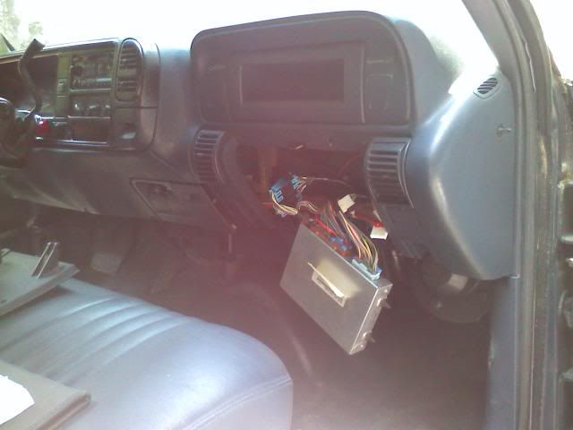
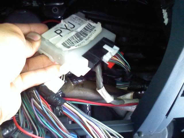
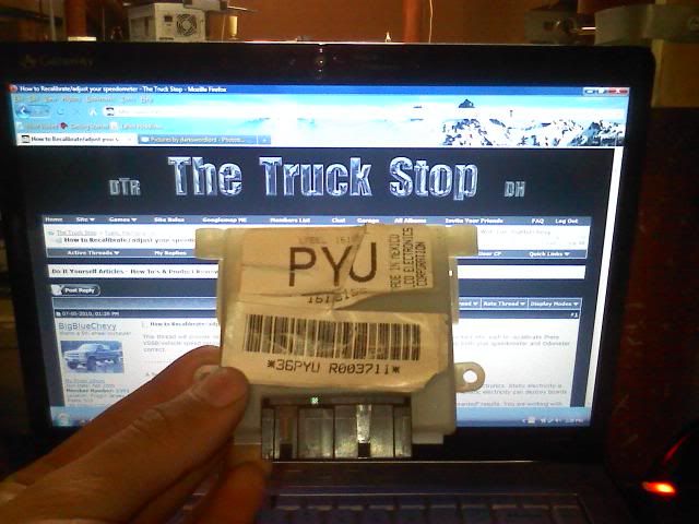
Start by locating and removing your VSSB unit. It will be located near the PCM, right underneath it(results may vary) The PCM is located behind the glovebox as show in the pictures below. Disconnect the wiring harness and remove the VSSB. Its only held in by 3 clips so pulling on the case a few times will get it loose.
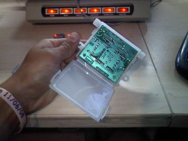
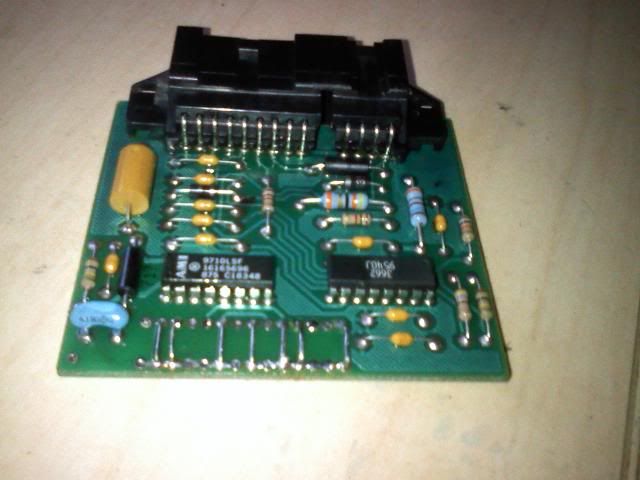
Once you have the VSSB in hand, bring it to a safe location and remove the PCB from the protective white case. there are two clips on either side, push them in and the case backing will flip right up.
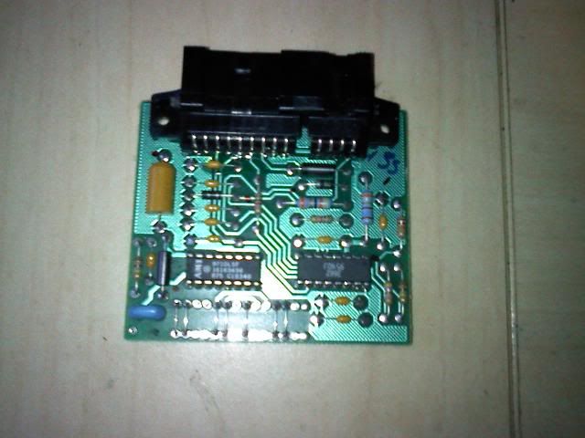
Remove the PCB by pushing up and away on the black connector protruding from the plastic. When handling the board, try to only contact the plastic connector. This will help avoid accidental static discharge.

Now the fun part. The pins/jumpers that we will be adjustming are located on the bottom of the PCB. But first, use the following charts, and websites to gather all of the technical data you need before melting any solder.
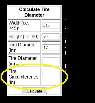
Using the above website. Enter your tire information. As you can see in the example below, my tires are a 315/70R17. Input those into there respective boxes and click calculate. The information you want is the "tire Circumference(in=)". Which I've circled below in the example. Another example:
-A stock 245/75R16 tire will have a rolling circumference of 95.8"
-A slightly larger 265/75R16 will have a rolling circumference of 99.3"
Now, you will need to take all of this new found info and add it all up. This can be done with the formula on the following page labeled "input ratio":
http://www.tbichips.com/drac/
Your going to want to use a scientific calculator to perform this equation(for the parenthesis). Most computers these days have calculators that can be run as a scientific type.
The forumla will look something like this on a calculator:
(63360X4.10X40) "DIVIDED BY" (108.1X128000)
Your formula will differ than mine depending on your gearing ratio and tires rolling circumference, but if done properly you will have a long number to compare to the chart on this page labeled Jumper settings It is the third chart from the bottom of the page.:
http://www.tbichips.com/drac/
My input Ratio came out as 0.750971323. Compared to the chart on the page linked above, I will have to arrange my jumper's as followed:
1 2 3 4 5 6 7
I 0 I I 0 0 I
I= jumper needed.
0= left open.
---------------------------------------------
A few early precautions.
- Whenever you work with electronic equipment(specifically the PCB) you are dealing with extremely sensitive electronics. Static electricity is FATAL to electronics. Do not touch any of the solder joints with your hands or other tools not ESD safe. Static electricity can destroy boards and you won't feel a damn thing.
- Avoid excess solder, bridging a solder connection between two solder holes can cause damage and "unwanted" results. You are working with parts normally assembled by either machinery or under microscope. Always double check your work.
- Adding the DIP switches to replace the jumpers is not really required. Although, for those who switch tires sizes often or own 2 different sets of tires(say drag and street, or summer and Snow) it is a very worthwhile investment. It will not be covered in this writeup however.
---------------------------------------------
Start by locating and removing your VSSB unit. It will be located near the PCM, right underneath it(results may vary) The PCM is located behind the glovebox as show in the pictures below. Disconnect the wiring harness and remove the VSSB. Its only held in by 3 clips so pulling on the case a few times will get it loose.
Once you have the VSSB in hand, bring it to a safe location and remove the PCB from the protective white case. there are two clips on either side, push them in and the case backing will flip right up.
Remove the PCB by pushing up and away on the black connector protruding from the plastic. When handling the board, try to only contact the plastic connector. This will help avoid accidental static discharge.
Now the fun part. The pins/jumpers that we will be adjustming are located on the bottom of the PCB. But first, use the following charts, and websites to gather all of the technical data you need before melting any solder.
- You will need to determine your gearing ratio in your differential(s). This can be done by checking the RPO codes located in your glovebox for one of the following:
- GU6. You have a 3.42 to 1 gearing ratio
- GT4. You have a 3.73 to 1 gearing ratio
- GT5/GT8. You have a 4.10 to 1 gearing ratio.
- HC4. You have the big daddy 4.56 to 1 gearing ratio.
- Next, you will need to determine your tires rolling circumference. Not as hard as you think, ahhh the power of the internet. Use the following website to input your tire info and get the rolling circumference you need:http://www.5speedtransmissions.com/calculators.html
Using the above website. Enter your tire information. As you can see in the example below, my tires are a 315/70R17. Input those into there respective boxes and click calculate. The information you want is the "tire Circumference(in=)". Which I've circled below in the example. Another example:
-A stock 245/75R16 tire will have a rolling circumference of 95.8"
-A slightly larger 265/75R16 will have a rolling circumference of 99.3"
Now, you will need to take all of this new found info and add it all up. This can be done with the formula on the following page labeled "input ratio":
http://www.tbichips.com/drac/
Your going to want to use a scientific calculator to perform this equation(for the parenthesis). Most computers these days have calculators that can be run as a scientific type.
The forumla will look something like this on a calculator:
(63360X4.10X40) "DIVIDED BY" (108.1X128000)
Your formula will differ than mine depending on your gearing ratio and tires rolling circumference, but if done properly you will have a long number to compare to the chart on this page labeled Jumper settings It is the third chart from the bottom of the page.:
http://www.tbichips.com/drac/
My input Ratio came out as 0.750971323. Compared to the chart on the page linked above, I will have to arrange my jumper's as followed:
1 2 3 4 5 6 7
I 0 I I 0 0 I
I= jumper needed.
0= left open.
")
 Used to work for an electronics company and they spoiled me with all kinds of great soldering equipment. Wish I had the solder vacuum they use there to remove solder from the holes, or hell at least solder wick. Didn't feel like fighting with the solder trying to slip the DIP switches in so I just said screw it. MY basement isn't exactly an ESD safe environment, so I didn't want to push it.