I've got fuel dripping from the bell housing hole and from areas around the interface between the block and bell housing when the truck is running. It took awhile to figure out what the fluid was because it was a small leak, and seemed weaker than diesel (watered down). I've exposed the injection pump, and the valley was wet, and the electric wires where wet, but not heavily like it should be if the pump was leaking, and fuel was pooling on top of the engine block. I have inspected the return line, and it seems good. I vaccumed and cleaned the area and there is a hole at the back of the engine block (looks like a drain). The leak started small, but, now, is not to be ignored. Another symptom that is occurring is...if the vehicle was to sit a day or more without being started it would take a long start or more than one try to start the vehicle (like air in the system). When the vehicle is at rest no fuel drips anywhere, so I can't pin point the leak, and the top of the engine is off. I think it is a leaking fuel pump, but I need to be certain. Has this situation occurred to others, if so, what was the remedy? Any an all information would be welcome, and don't spare the details....

Navigation
Install the app
How to install the app on iOS
Follow along with the video below to see how to install our site as a web app on your home screen.
Note: This feature may not be available in some browsers.
More options
-
Welcome to The Truck Stop! We see you haven't REGISTERED yet.
Your truck knowledge is missing!
- Registration is FREE , all we need is your birthday and email. (We don't share ANY data with ANYONE)
- We have tons of knowledge here for your diesel truck!
- Post your own topics and reply to existing threads to help others out!
- NO ADS! The site is fully functional and ad free!
Problems registering? Click here to contact us!
Already registered, but need a PASSWORD RESET? CLICK HERE TO RESET YOUR PASSWORD!
You are using an out of date browser. It may not display this or other websites correctly.
You should upgrade or use an alternative browser.
You should upgrade or use an alternative browser.
Fuel dripping from hole in bell housing and other areas
- Thread starter Tovar
- Start date
MrMarty51
Well-Known Member
Hello Tovar.
If Your truck still has the original relay for the lift pump, You should be able to remove the relay and jumper to two of the wires and cause the lift pump to run. Then, with the intake manifold removed You will be able to see where the leak is coming from, if it is on the low pressure side of the lift pump system.
If it is not the LP system, then, You will be able to start the engine and with the engine running determine where in the high pressure side the fuel is leaking from.
Please report back Your findings.
Have a look at the filter case, the round aluminum thing bolted to the back of the intake, their are "o" rings in a few places on the bottom part, they often leak.. and the rubber fuel lines should be replaced while your in their, they also leak...
MrMarty51
Well-Known Member
You can also use a remote battery and set it by the back of the cab and use a couple of jumper wires and jumper the lift pump, instead of having to jumper across the relay switch wires.
I have a modified relay from Leroy. Just push a button and the lift pump activates. I also have moved the FFM, and it is not leaking. Actually, the FFM (and entire fuel system) is still full and attached to the injection pump. This is my first time messing with the injection pump, and related areas. So, I've learned (the hard way) better to ask before going off in my own (especially, if someone has had the same problem, and fixed it). I know the leak is not occurring on the side before the fuel reaches the injection pump. Because I have visually checked several times before taking the vehicle apart. I have 9psi running to the injection pump, normally. So, the leak has to be occurring on the pump itself or the return which is located running to the back of the engine. Anybody know what that hole at the back of the block (in the valley) is for...? Is it a drain, so fuel will not pool on top of the engine? So, I can start the engine (or bump) with the two intake manifolds off, disabled glow plugs, exposed turbo, etc., fuel is still hooked up, but I don't want to cause more damage. This is new territory for me... That is why I'm asking....
Paveltolz
Доверяй, но проверяй
Removing the upper and lower intakes and clean the lines, pump and the FFM first with some Dawn/Water mix so with everything clean and dry, the leak will manifest itself easily. Running the pump either 'key on,' jump or engine start), will allow you to see what's happening. Won't hurt to run the engine with intakes off. Just be sure to keep rags, bolts, nuts, debris etc. away from the intake holes (been running mine like that trying to get the IP timed for the last week). Check the return hose at the front of the IP, the return line off the FFM and inspect the IP for any weeping on the pump or the injection lines (rare I'm sure but, it can't hurt). Good luck.
Hole on the back of the block is as you said, a drain hole.
Hole on the back of the block is as you said, a drain hole.
And to add to what Paveltolz has said , depending on the year there is a drain tube that is bolted to the back of the block running from the upper drain hole to another hole by the oil cooler lines . I've seen the tube on the 6.5 but not on the 6.2 .
Thanks Paveltolz and EWC. With that information, I'm pretty sure I know where the leak is coming from. I will run the engine like Paveltolz described and verify. But, now, knowing that is a drain hole my money's is on the pump weeping.
Will L.
Well-Known Member
Fingers crossed for ya.
Wreckinball67
Well-Known Member
- Messages
- 134
- Reaction score
- 314
If you could report back with a few photos, that would be awesome.
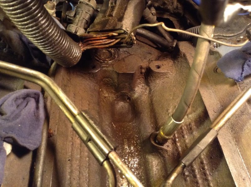
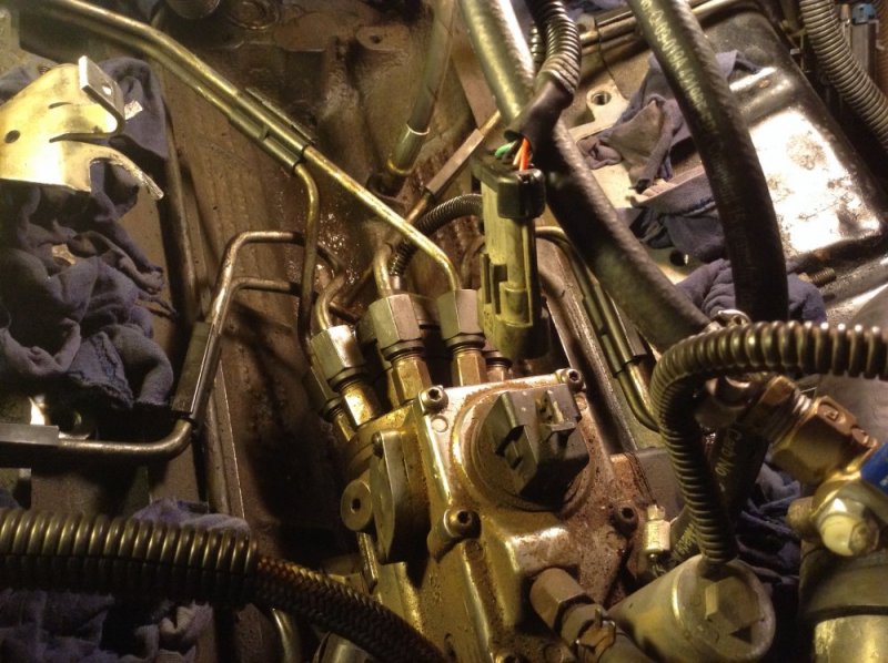
Started the truck today (made sure nothing got into the open holes). Findings.... The injector pump has an obvious leak underneath the back end (cylinder area where the octopus arranged injector lines are attached). Good thing that there is a drain hole located on the back of the block in the valley (this is a 1999 Chevy), or the leak would have created a huge mess. But the fuel just drained right on out, and onto the ground through the hole located on bottom of the inspection plate. So, I need to replace the injector pump. It will be the first time for me for this particular chore. Anybody have a link to a very detailed procedure for this job? Don't spare any details no matter how small you may think they are. Also, what would be the best way to bleed the fuel system after the install....?
Attachments
ak diesel driver
6.5 driver
I'd be double checking all the fittings are tight and that you don't have a hole in an injector line
Will L.
Well-Known Member
Yes, Be 100% sure it is leaking from the weep hole. SO MANY ip get changed and afterwards the problem still exists, then a minor issue is found later.
There is a military manual in pdf WarWagon posted here iirc. Follow those instructions, except I say pull the glowplugs. Then use the lift pump to prime line. Then crank until you see a mist coming from the glow plug holes. It will crank really fast and prime/ bleed easy that way.
Many people choose to do new injectors with the new ip, but I say if you do that get it running with the new ip first. Then go in and do the injectors.
While your at it good time for FTB mod and adding pressure gauge. I would say pressure gauge before doing ip
Paveltolz
Доверяй, но проверяй
Hose that IP down with some brake cleaner and blow it off then re-start to confirm weep hole. Get a mirror or a Bore Scope (maybe the local parts guys have loaner?)
I built a PDF from the pages of the GM Shop manuals along with some notes of my own for swapping IP and injectors (currently in the middle of my own swap only with a new rebuilt IP that WILL NOT SET TDCO or TIME...I digress). The file is too large to post here but can be emailed. Additionally, I may be heading to Tucson shortly, if the Military Travel Restrictions ever get lifted, where are you in AZ?
I built a PDF from the pages of the GM Shop manuals along with some notes of my own for swapping IP and injectors (currently in the middle of my own swap only with a new rebuilt IP that WILL NOT SET TDCO or TIME...I digress). The file is too large to post here but can be emailed. Additionally, I may be heading to Tucson shortly, if the Military Travel Restrictions ever get lifted, where are you in AZ?
Last edited:
ak diesel driver
6.5 driver
crowsfoot
Paveltolz
Доверяй, но проверяй
A cut 19mm will get most of them but, you'll need a crows foot for the two bottom ones (4&5). To get the nut off the driver's side what with the AC compressor and all in the way, I use a 12 pt. Socket on a couple of long extensions and come at it from darn near the fire wall.
Be sure to make a reference mark on the IP and Engine housing and transfer it as close as possible to the new pump so it will be pretty close to timed when you tighten down the new pump.
Be sure to make a reference mark on the IP and Engine housing and transfer it as close as possible to the new pump so it will be pretty close to timed when you tighten down the new pump.
Husker6.5
135' diagonal 16:9HD, 25KW sound!
Or just use a 19mm flare nut wrench. Once you have the upper nuts off and the lines loose, it's easy to slip the flare nut wrench down over the line and onto the nut and break them loose and remove them.
This video notes you can remove the IP gear bolts through the oil filler hole. You can't mess the gear timing up as there is NOT enough room in the housing to allow the gears to unmeash and jump time. DO NOT DROP THE DAMN BOLTS! Or you are going into the engine after them. Note the IP position, don't whirl it for shits and grins, and match up the new pump's shaft to the old one. Makes reassembly lots quicker.
ME? I like to spin the old IP for fun times putting it back together.
ME? I like to spin the old IP for fun times putting it back together.
How to change IP: 1981 introduction VideoDisc for the GM 6.2 V8 diesel
This is the quickest way to swap an IP shown in the video. The 2nd fuel filter location and procedure to change looks to be and is a nightmare to change. (I dunno if that made it to production.)
www.thetruckstop.us
Back on line....Here is what I had to do....
1) remove passenger side battery.
-unhook driver side battery neg cable.
2) drain down coolant enough to remove top radiator hose (radiator drain area may need modification to access easily).
3) remove top fan shroud, fan / clutch, serpentine belt, crank pulley, oil intake and gasket (plug hole w/rag).
4) remove turbo and accessories, air box and accessories, passenger side battery holder and fender.
5) remove upper intake manifold (six 10mm; install torque 17 ft/lbs).
6) remove lower intake manifold (15mm; install torque 31 ft/lbs).
-keep bolts arranged as they come out on piece of cardboard.
-install manifold bolts finger tight...tighten in increments starting with the inner bolts using a crisscross pattern to finish torque 31 ft/lbs.
- when intake manifold is off, plug holes.
7) remove/plug FFM fuel line to IP intake, IP return, and FFM drain.
8) remove IP fuel hard lines:
-passenger side of engine are cylinders 2,4,6,8.
-driver side of engine are cylinders 1,3,5,7.
-follow and lable the hard lines to the connectors on the IP.
-start with removing 1-3, then 2-6, then 4-8, then 5-7.
-install in the reverse order.
-install torque 24ft/lbs. (both ends).
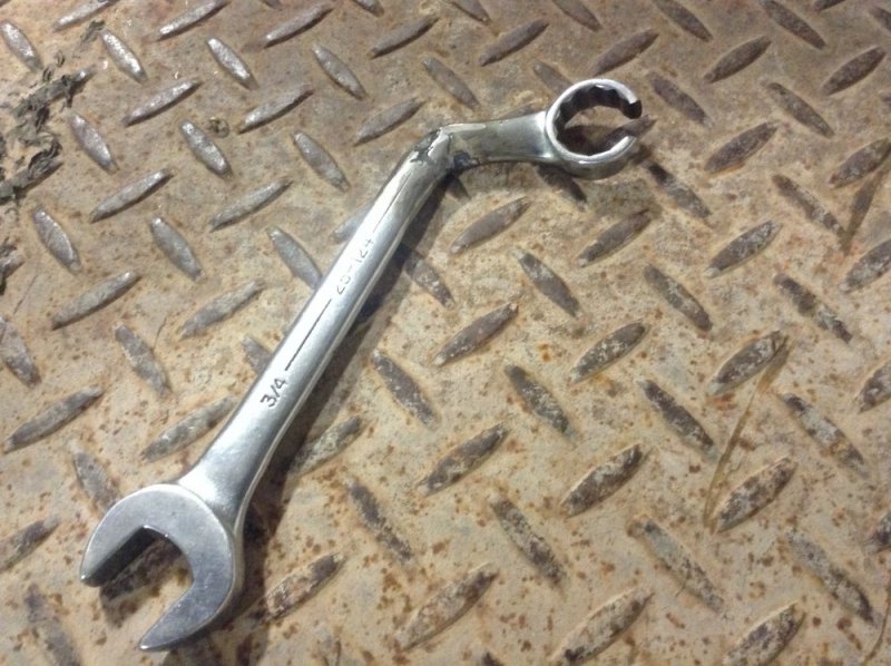
Tools: I modified a 3/4" wrench by bending it and cutting a slot in the box end (see picture).
9) clean area around where the IP is inserted into the drive gear box.
-make indicator marks on the IP and where it inserts into its housing.
-want to put the new IP back into the same place as the old one. This keeps the pumps timing.
10) To remove pump:
-remove the front 3 bolts through the oil intake hole.
-find the first bolt by rotating the crank clockwise by the crank bolt (15/16").
-stuff the bottom of the hole with paper towel.
-loosen bolt, then hand remove until bolt is free.
-before removing, trap the bolt against the socket using your finger.
-repeat process for each bolt (remove paper towel for each engine rotation and then restuff).
To replace front bolts:
-same process, but use grease in the socket to hold the bolt in the socket (install torque 20 ft/lbs).
Next:
-remove the back three nuts...bottom two first, then the top. Then, slide the IP back and out (install torque 30 ft/lbs).
-note the pin on the IP front, orient the new pump pin face the same as the old pump. Since the pump turns counterclockwise while on the engine...twist the new pump face counterclockwise to orient the pin.
-transfer indicator marks on the old pump to the new pump as close as possible.
-insert new pump; using the top nut first, orient marks and tighten all three nuts (30ft/lbs).
To bleed the system:
1) reinstall everything except the passenger side fender. So, air and battery box will be left off.
2) disengage the glow plug relay and all associated wires, remove all eight glow plugs.
3) temporarily install the battery box by using one bolt on the inside wall and a jack with a 2 by 4 (cut to fit).
4) have all batteries charged and hook up.
5) make sure fuel system is bled from tank to new IP intake (use lift pump).
6) have a spotter...spin engine at 30 second intervals (rest starter) until a fuel mist comes out of all eight glow plug holes.
7) reinstall glow plugs and whole glow plug system.
8) reinstall everything...engine and engine compartment should be completely restored.
9) start truck normally, should start up within 3-4 seconds of cranking.
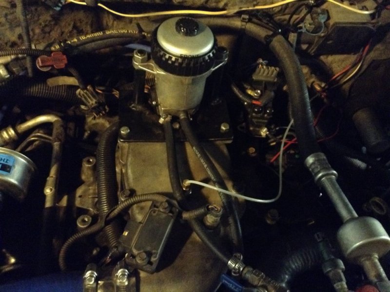
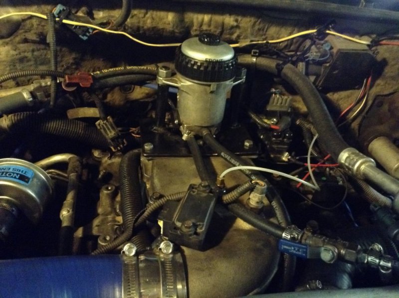
I modified my FFM, moved my glow plug apparatus, OPS, and wire harness up and out of the "valley" (see picture).
1) remove passenger side battery.
-unhook driver side battery neg cable.
2) drain down coolant enough to remove top radiator hose (radiator drain area may need modification to access easily).
3) remove top fan shroud, fan / clutch, serpentine belt, crank pulley, oil intake and gasket (plug hole w/rag).
4) remove turbo and accessories, air box and accessories, passenger side battery holder and fender.
5) remove upper intake manifold (six 10mm; install torque 17 ft/lbs).
6) remove lower intake manifold (15mm; install torque 31 ft/lbs).
-keep bolts arranged as they come out on piece of cardboard.
-install manifold bolts finger tight...tighten in increments starting with the inner bolts using a crisscross pattern to finish torque 31 ft/lbs.
- when intake manifold is off, plug holes.
7) remove/plug FFM fuel line to IP intake, IP return, and FFM drain.
8) remove IP fuel hard lines:
-passenger side of engine are cylinders 2,4,6,8.
-driver side of engine are cylinders 1,3,5,7.
-follow and lable the hard lines to the connectors on the IP.
-start with removing 1-3, then 2-6, then 4-8, then 5-7.
-install in the reverse order.
-install torque 24ft/lbs. (both ends).
Tools: I modified a 3/4" wrench by bending it and cutting a slot in the box end (see picture).
9) clean area around where the IP is inserted into the drive gear box.
-make indicator marks on the IP and where it inserts into its housing.
-want to put the new IP back into the same place as the old one. This keeps the pumps timing.
10) To remove pump:
-remove the front 3 bolts through the oil intake hole.
-find the first bolt by rotating the crank clockwise by the crank bolt (15/16").
-stuff the bottom of the hole with paper towel.
-loosen bolt, then hand remove until bolt is free.
-before removing, trap the bolt against the socket using your finger.
-repeat process for each bolt (remove paper towel for each engine rotation and then restuff).
To replace front bolts:
-same process, but use grease in the socket to hold the bolt in the socket (install torque 20 ft/lbs).
Next:
-remove the back three nuts...bottom two first, then the top. Then, slide the IP back and out (install torque 30 ft/lbs).
-note the pin on the IP front, orient the new pump pin face the same as the old pump. Since the pump turns counterclockwise while on the engine...twist the new pump face counterclockwise to orient the pin.
-transfer indicator marks on the old pump to the new pump as close as possible.
-insert new pump; using the top nut first, orient marks and tighten all three nuts (30ft/lbs).
To bleed the system:
1) reinstall everything except the passenger side fender. So, air and battery box will be left off.
2) disengage the glow plug relay and all associated wires, remove all eight glow plugs.
3) temporarily install the battery box by using one bolt on the inside wall and a jack with a 2 by 4 (cut to fit).
4) have all batteries charged and hook up.
5) make sure fuel system is bled from tank to new IP intake (use lift pump).
6) have a spotter...spin engine at 30 second intervals (rest starter) until a fuel mist comes out of all eight glow plug holes.
7) reinstall glow plugs and whole glow plug system.
8) reinstall everything...engine and engine compartment should be completely restored.
9) start truck normally, should start up within 3-4 seconds of cranking.
I modified my FFM, moved my glow plug apparatus, OPS, and wire harness up and out of the "valley" (see picture).