• Welcome to The Truck Stop! We see you haven't REGISTERED yet.

    Your truck knowledge is missing!
    • Registration is FREE , all we need is your birthday and email. (We don't share ANY data with ANYONE)
    • We have tons of knowledge here for your diesel truck!
    • Post your own topics and reply to existing threads to help others out!
    • NO ADS! The site is fully functional and ad free!
    CLICK HERE TO REGISTER!

    Problems registering? Click here to contact us!

    Already registered, but need a PASSWORD RESET? CLICK HERE TO RESET YOUR PASSWORD!

DS4 max fuel rates at X rpm

OK, I got mixed up with my math (as usual long plug and chug I end up making an error). At 3400 rpm you would get 2x the amount of fuel per minute since 2x the rpm of 1700. But same per revolution Duh. However, the rate of camring/plunger lobe pump action is 2x as fast so I still believe the peak line pressure is at least 2x as much at 3400 rpm than at 1700 rpm. I bet timing of the solenoid closure would affect the internal IP pressure too

I think the issue is not whether the motor can take the extra fuel and timing issues (surely it can since propane doesn't kill engines). I think its if the IP drivetrain doesn't shear off the drive pin ????? When max fuel rates are delivered at high rpm depending on injector orifice timing and setup etc. What else might affect it?

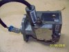
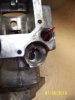
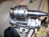
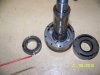
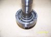
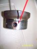
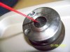
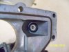
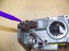
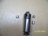
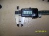
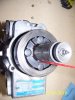
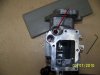
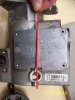
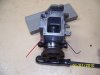
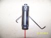
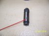
I have a DS4 IP in pieces and measure approximately (calipers) the plunger at 0.375" dia. The cam ring diameters are 1.956" big to 1.906" small.

If I am understanding this right....
There are 4 plungers and 8 lobes. One pump high to low cam position would be .375" diam x .1" long (diameterically opposed plunger 2x radial stroke). It will do this 4 times per rev of the IP rotor.

So lets try and calculate what it could theoretically pump through IF all the fuel could be injected.

I think the IP turns at 1/2 crank speed right ?

92mm^3 per 1000 strokes is what per each cam lobe stroke (4 per IP rotor rev) or per rev of the IP rotor???
 
Last edited:
Well.... Its not going to be necessarily linear at all since the pop pressure is going to bias low flowrates vs high but I still think the orifice size of the injector might be major limiting factor for peak line pressure at high fuelrates.
 
How about some pics there Schiker? Be nice to see the inside as well as some labels as to what were looking at
 
I'll try and take some pics first of next week. My weekend is already full.
And don't get your hopes up my photography isn't that good.

I'd like to know what some more of the mechanics are of the cycle. Some of my thoughts are 1/2 of the stroke is for injection and 1/2 is for internal recirculation and the transfer pump mechanism often spoke of or something. ?????

I was just able to get the optic sensor out so I can dig a little more Monday too so more might get clearer.
 
Yeah right like anyone has free time at this time of year. I'll try and take some pics after the holidays. I have taken more apart but broke an allen wrench and a torx bit. These IP's fasteners are tight.

SmithvilleD pointed me to this site for some pics and article.


http://flashoffroad.com/Diesel/injec...ectionpump.htm

I quickly read the above article and its ok more about optic bump related but has key components pictured. I still haven't found a good source for fill - spill chamber flow logic yet.

I did finally get to I think a rotary vane pump mechanism that I think is the "transfer pump". Also the inlet fitting has a checkvalve that appears to be ported from I guess the plunger area I'll have to check that again. Still trying to fiqure it out a little more before I post pics and thoughts better.

how about this one

http://flashoffroad.com/Diesel/injectionpump/injectionpump.htm
 
Last edited:
Here are some pics as promised I'll try and add more later.

that is the top off showing the fuel shutoff solenoid and inlet passage. The FSOS closes the inlet to the transfer pump a rotarty vane pump.
 

Attachments

  • dsip 018.jpg
    dsip 018.jpg
    45 KB · Views: 8
  • inletFSOS-seat.jpg
    inletFSOS-seat.jpg
    33.2 KB · Views: 9
transfer pump pics This is the main shaft of the pump Red straw in first pic indicates inlet. This is the passage just below the seat of the FSOS mentioned before.

It pumps the inlet supplied fuel and insures the plungers pumped with fuel or charges the plungers. I think they will pull a little fuel themselves but the transfer pump pushes them out and force fills them I think.

Rotary vane pumps are pretty strong as long as they are "wet" and what allows the truck to run with an inoperable lift pump.

NOTE I have not had any IP schooling just supposing this is how it should work.
 

Attachments

  • transferpump1.jpg
    transferpump1.jpg
    50.4 KB · Views: 12
  • transf-pcs.jpg
    transf-pcs.jpg
    47.6 KB · Views: 9
another shot of internal to the transfer pump.

Try wikipedia for how a rotary vane pump works. They have an animation of a pump.
 

Attachments

  • vanes.jpg
    vanes.jpg
    43.4 KB · Views: 6
Last edited:
the transfer pump then is ported to the fuel distributer. Where all the injection lines attach to back of the pump. You can just see the inlet ports through the outside hole in the 3rd pic.

The 4th pic show the outlet ports leading to the injector ports then lines and on to the injectors. The straw in 4th pic points to the inlet and you can see the outlets farther in the bore. This view is from inside the IP looking out of the distribtor bore. The lines attach to the face on the floor.

******
Edit I think I got mixed up the 3rd pic is actually I think is the return port I will verify soon. The inlet from transfer pump is on other side and looks similar. Its the devil in the porting and timing. I will hopefully show its either excess or when inlets of the rotor do not align or both allow the transfer to pump directly through back to the inlet or to camring area. Hopefully can also show excess that is not injected is pumped through to the cam ring area and available to return to tank when enough pressure trips the return checkvalve.
 

Attachments

  • dsip 008.jpg
    dsip 008.jpg
    45.9 KB · Views: 4
  • dsip 023.jpg
    dsip 023.jpg
    48.7 KB · Views: 4
  • dsip 013.jpg
    dsip 013.jpg
    33.2 KB · Views: 6
  • dsip 011.jpg
    dsip 011.jpg
    42.7 KB · Views: 5
Last edited:
the return is in top of ip and a check valve mechanism should open at about 15 psi I have read iirc not sure about that though.
 

Attachments

  • dsip 006.jpg
    dsip 006.jpg
    39.2 KB · Views: 5
  • return.jpg
    return.jpg
    45.9 KB · Views: 5
Put it back together ha ha ha. Not with all the kings horses and men. Some of the pieces are missing to boot. I took it apart a good while back and did not take any notes or pics and tore into it like a kid at christmas to see inside. It was fishbiting and I bought it for postage. I wanted to look at the metering mechanism and then try to figure out a few things. If anyone wants a specific area or item pictured let me know.

The timing of the distributor and porting is really the key and I can't really get them in pics. Plus I am not sure exactly myself. I think I got the jist of it but can't get the distributor apart and even then I'd need to sit down and look at sequence over and over to feel like I fully understand. I am going to try to take a few more shots of the rotor and plungers and some of the return path??? when I get some more free time.
 
I was reading some of 6.2s posts about his 1/2" plungers would like a good closeup of a plunger and it's mating hole. If it's not too hard to machine a guy might go bigger in a more conservtive manner and see some good hp gains
 
I was reading some of 6.2s posts about his 1/2" plungers would like a good closeup of a plunger and it's mating hole. If it's not too hard to machine a guy might go bigger in a more conservtive manner and see some good hp gains

OK. No way 1/2" dia will fit the DS pumps that has to be a 2 plunger DB pump???? Not much meat left in rotor for bigger diameter plungers.
 
Smithville I hope I am not hijacking your thread too far and hopefully it relates.

Ok plungers are diameter 0.310" (7.87 mm). Cam ring large diameter is 49.68mm small is 48.41 mm one cam stroke is then - 0.635mm

so 4 plungers at area of plungers x stroke = displacement. My math comes out at 120 mm^3 per displaced per cam stroke. ????

I lost one plunger and think it was similar to the long one. The rotor and plungers are pic 1. plunger dia in pic 2. the cam ring aroung the rollers, shoes, and red straw pointing to plunger.

AK the plungers start to get close on inside and may have limitations of length to diameter ratios or other restrictions. I have read blurbs the physical limits are not too far away with the design. Can't remember if its the cam lobe rise rate or stroke or other issues.
 

Attachments

  • dsip 043.jpg
    dsip 043.jpg
    39.9 KB · Views: 3
  • dsip 053.jpg
    dsip 053.jpg
    45.7 KB · Views: 4
  • dsip 050.jpg
    dsip 050.jpg
    44.2 KB · Views: 8
Last edited:
transfer flow path...???

Ok here is part of the path. There are other paths too I will try to explain later. THe tranfer pump flow comes down the right side of pump in pic 1 and ported through in the allen wrench area to fuel distributor inlets. This is also connected to the excess feed line on left with straw then goes underneath the PMD pad mount through a check valve in the bottom of inlet back to the transfer pump inlet.

A positive displacement pump pumping fluid has to have a relief and when the plungers are full or inlets are blocked due to time of ports then this is one exit for the pump pressure so it is not "dead headed"
 

Attachments

  • dsip 032.jpg
    dsip 032.jpg
    47 KB · Views: 5
  • dsip 016.jpg
    dsip 016.jpg
    34.5 KB · Views: 4
  • dsip 034.jpg
    dsip 034.jpg
    44.6 KB · Views: 4
  • dsip 031.jpg
    dsip 031.jpg
    46.6 KB · Views: 4
plunger charge

Pic 1 shows the inlet ports of distributor. There are 8 and align with the rotor inlets shown in pic 2 they are at an angle to encourage flow towards the plungers

Now I am supposing once plungers are filled excess flow is returned to either the bottom of inlet with a checkvalve relief valve in it or to the cam ring area which also has the return fitting with a relief valve checkvalve Mentioned earlier has an opening pressure I think is at 15 psi ish iirc . Such that the transfer pump will have a max associated charge pressure for the plungers.

All entrances to the plunger charge stroke are check valved and if the transfer pump is not charging the plungers they can't float out to the cam ring lobe large diameter. So that for shut down emergency the FSOS closes and won't allow the plungers to charge then the fuel injection charge will run out and the engine will quit.

Picture 3 show the port leading to the injectors there is only one and its enlongated so that the ports will align during the injection event (as the cam lobe rises and to accomodate difference in timing I suppose).
 

Attachments

  • dsip 011.jpg
    dsip 011.jpg
    42.7 KB · Views: 1
  • dsip 041.jpg
    dsip 041.jpg
    40.3 KB · Views: 1
  • dsip 042.jpg
    dsip 042.jpg
    42.4 KB · Views: 3
Last edited:
Back
Top