btsayles
Diesel Proficient
Hi, everyone.
I've been away for a couple of years obtaining a mechanical engineering degree and working full time, which didn't leave much time for fun things (as in zero). Well, that's all over with now, and I have time to play. I have learned tons of stuff from this forum over the years, and I appreciate it a great deal. Thank you all. I have done a search for people trying to repair the PMDs on the forum and didn't readily find anything. If I just missed it, tell me and I'll stop.
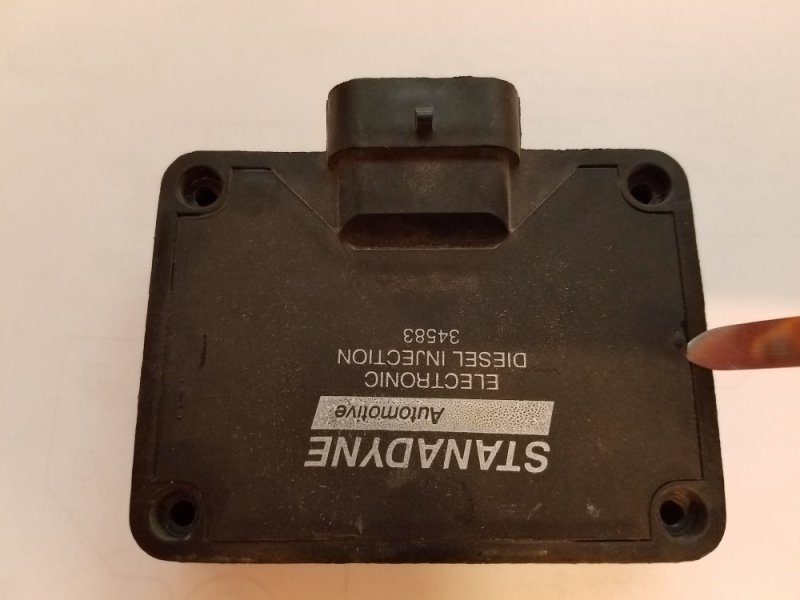
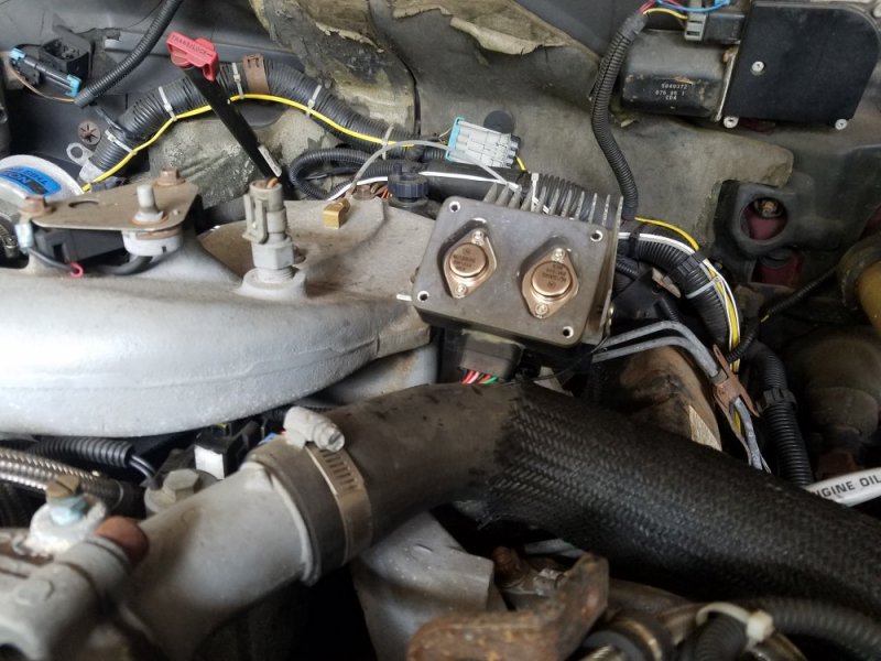
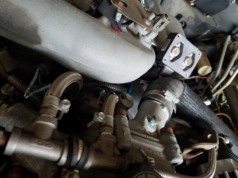
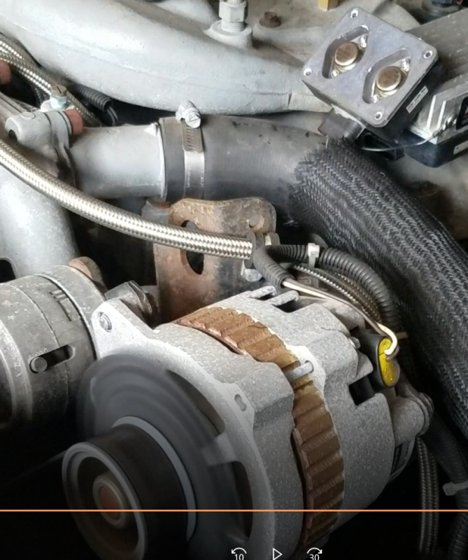
I've been lucky with PMDs over the years, and have taken all of the recommendations of having a spare in the truck to heart. My '95 6.5l shut off at the intersection outside of a store, and started up upon cranking. I immediately pulled into the first lot I came across (50 ft) where I shifted (automatic) into neutral. Upon neutral the engine ran away for 2 seconds and died again. Prior symptoms were a miss from time to time, but I know that can be from all kinds of things. I have my PMD remote mounted on a heat sync, and this last PMD has been alive for 5-7 years.
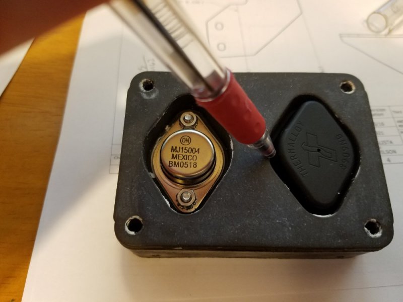
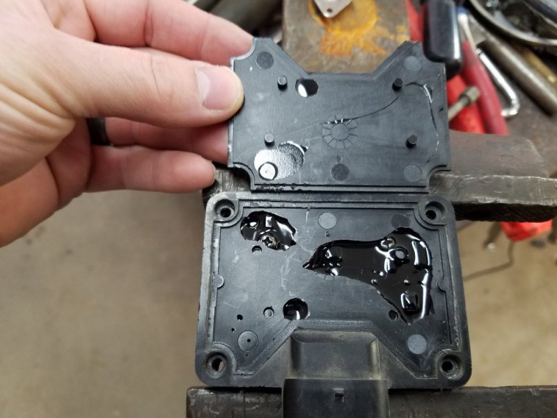
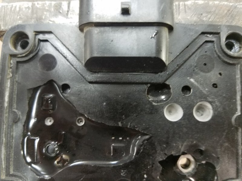
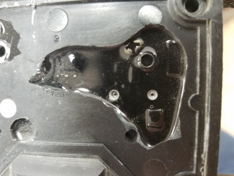
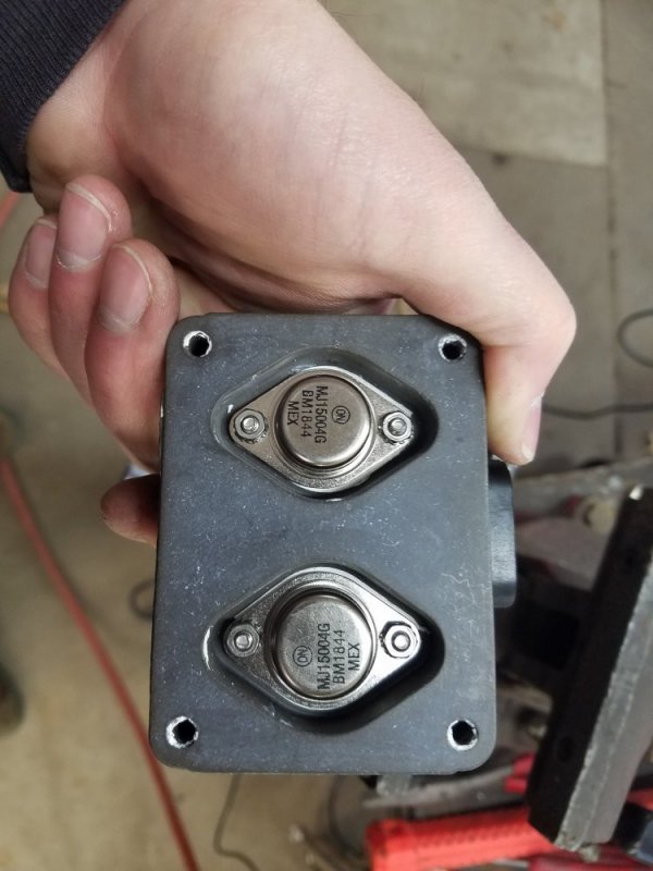
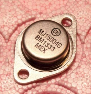
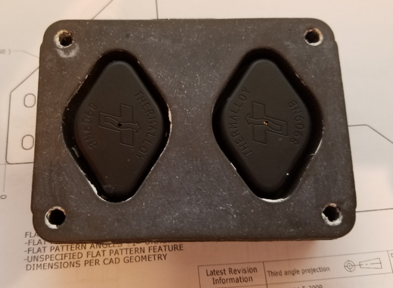
I am not concerned with the cost of a lifetime warranty on these, but since I had a bad one, I figured I would replace the transistors and see if that would fix it. I watched a ytbe video on some guys hacking their PMD with a small rotary tool and was curious about how they didn't hack up their circuit board the transistor was soldered to. Like a dope, knowing it was going to be nearly impossible to cut through the black, solid, opaque potting without damaging the circuit board, I tried to drill the transistor pins down through the board. It worked, but like crap and was a arduous process. I saw where I had damaged the CB in other locations as well. Oh well, I enjoyed myself. Destroying things is fun at times.
I got to thinking, every video I have seen of people trying to replace these transistors has ended the same way, nothing; there is never a, it worked like a champ with a running truck. That should be the first clue, right? If someone was really proud of their work, they would show the last clip of the video of a revved up turbo whistle.
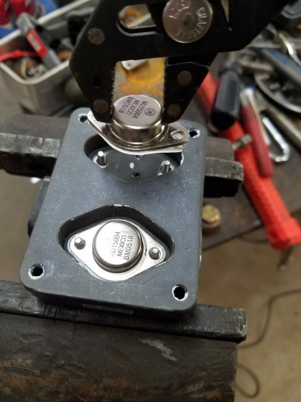
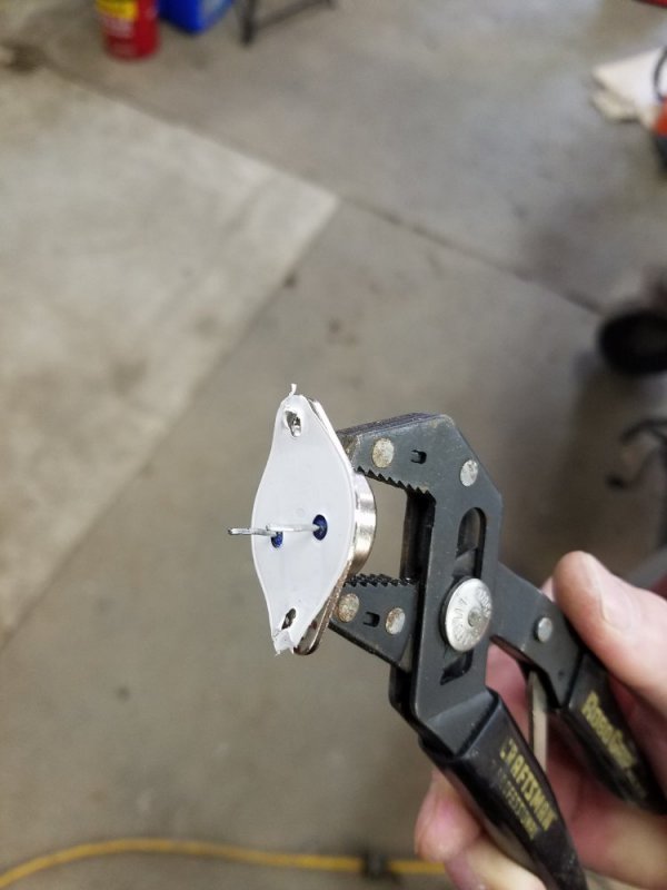
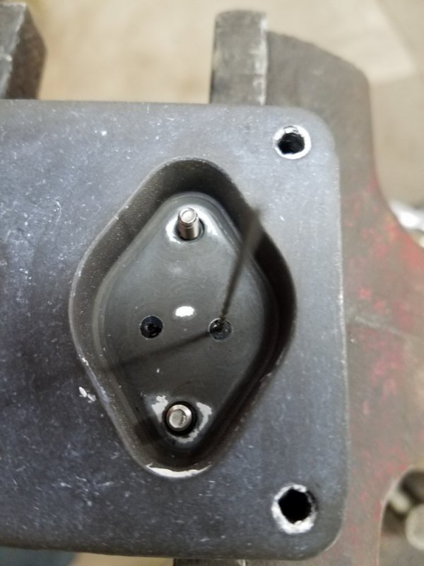
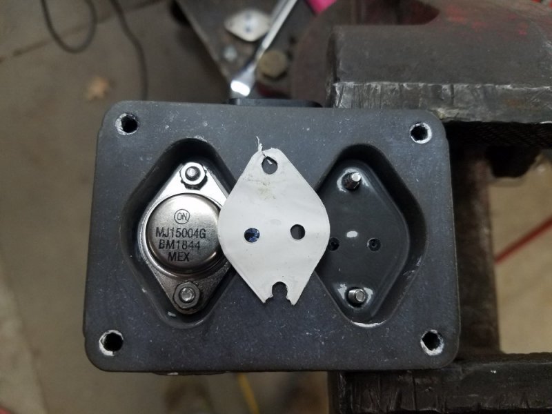
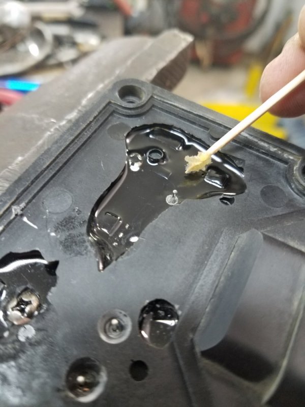
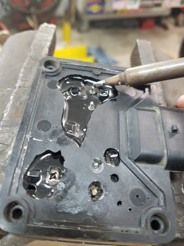
I have a FUBAR PMD to practice on now. I grabbed the other transistor with a pair of C-man robo-grips (which I haven't used in like 15 years) and rocked and pulled on the transistor until it withdrew from the PMD. Trust me, this was not easy, but with a little patience, both pins slid out of the PMD with the transistor. Since there is nothing above the transistor pins on the PMD circuit board (CB), with no pin debris in the pin hole in the potting and CB, I used the pin holes as drill guides. With the PMD cover removed I drilled right up through the potting. Now I had guide holes to get me right back to the CB. I took a chamfer in a drill and followed the hole back down a touch at a time until I reached the CB pin soldiering location. This action is precision work, but very doable with the guide hole created.
Naturally, I'm not going to install good transistors into a part I know is junk. I'm sure after reading this, I'm sure some of you are going to try to replace some transistors.
The reason I went through this long explanation is because I am trying to beg for a couple of PMD to verify this actually works on. I'm not trying to make any money on this; I am just trying to give back to the great people of this forum who have helped me out of a few jams in the past. Once I verify the results, I will post a "how to" with clear pictures, instructions (including the parts and what the G means (contains no lead)), who that does not matter, and a running truck with the actual repaired PMD, covers off, to you, this forum.
I hope to not get hate mail or death threats because of this. Hope you all are having a great day. Please send me a PM if you have some dead PMDs I can toy with. I'd be happy to send a paypal gift for shipping. Thanks.

