• Welcome to The Truck Stop! We see you haven't REGISTERED yet.

    Your truck knowledge is missing!
    • Registration is FREE , all we need is your birthday and email. (We don't share ANY data with ANYONE)
    • We have tons of knowledge here for your diesel truck!
    • Post your own topics and reply to existing threads to help others out!
    • NO ADS! The site is fully functional and ad free!
    CLICK HERE TO REGISTER!

    Problems registering? Click here to contact us!

    Already registered, but need a PASSWORD RESET? CLICK HERE TO RESET YOUR PASSWORD!

6.2/6.5 How to Rebuild Your Starter

Status
Not open for further replies.

bison

Well-Known Member
Messages
5,701
Reaction score
144
Location
Near Peace River-Alberta
Lets take it apart.

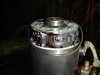
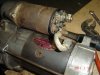
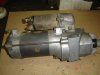
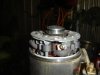
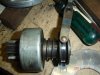
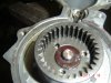
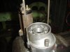
Pic 1) the gear reduction starter as we all know it.
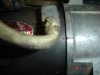
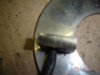
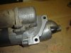
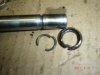
P 2) One can clearly see the shiny narrow part between the mounting bolts where the starter contacts the block,no wonder that the little bracket on the rear of the starter is must to keep the starter steady to the block. Without it there is just to much force on the 2 bolts to keep them from fatiqueing and then breaking off.
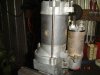
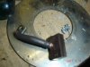
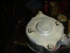
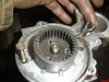
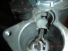
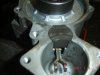
P 3) Take out the 2 little screws( there's an 0 ring on them) holding the brush holder( inside) to the end cap.
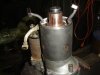
P 4) unbolt the cable from the field housing to the solenoid(forgot pic) and take the 2 long trough bolts out .

I'm missing pictures,and they are not in order either.i don't know why?
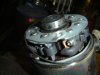
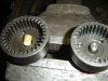
Tap the end cap loose with the hammer,the brush holder will stay in place.
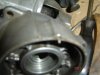
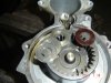
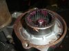
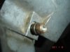
There is an 0 ring on the field housing as you can see in the bottom center right pic.

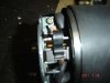
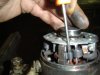
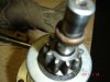
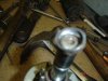
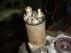
There are 4 brushes in all.2 of them are attached to the fields and have to be taken out of their spring loaded slots by prying the spring outwards with a suitable tool.A small screw driver like you see in the bottom pic works best.

The other 2 brushes can pulled out a bit and be wedged between the slot and the spring like in the bottom pic..
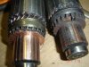
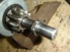
Now you can take the brusholder off the armature, and pull the armature straight up and out.
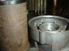
With a little tap to the side the Field housing can be removed as well.(there's a small dowel in between the intermidiate housing and the field housing,don't lose it.(it will show in the next couple pics)

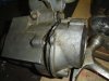
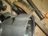
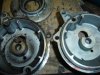
Bottom pic)Take the 2 bolts out that hold the housing to the nose cone and pry the halves apart,Tapping on both sides to get some room for a screw driver to pry with.

More later
 

Attachments

  • GM starter 001.jpg
    GM starter 001.jpg
    40.5 KB · Views: 57
  • GM starter 002.jpg
    GM starter 002.jpg
    43 KB · Views: 50
  • GM starter 003.jpg
    GM starter 003.jpg
    39.2 KB · Views: 46
  • GM starter 004.jpg
    GM starter 004.jpg
    37.6 KB · Views: 49
  • GM starter 006.jpg
    GM starter 006.jpg
    45.3 KB · Views: 54
  • GM starter 007.jpg
    GM starter 007.jpg
    47.8 KB · Views: 53
  • GM starter 009.jpg
    GM starter 009.jpg
    37.5 KB · Views: 52
  • GM starter 016.jpg
    GM starter 016.jpg
    46.3 KB · Views: 48
Last edited:
Top left ,shows spacer washers in the ring gear.

Top right is the armature.

5 th down left,the brush contact area,this one needs just cleaning up.

third down left brush spring held with a nut to prevent having to dig it up out of the slot(don't allways work)

4th down, left, after removing the solenoid, the rubber stop and underlyingplate can be pried out.and the fork pivot bolt taken out(pic 3 down right)
pic 5 down ,rightThen tap the housing on a block of wood to unseat the starter drive assembly.
pic 2 down,left .Assembled starter drive,gear shaft and gearshaft bearing support).
The fork comes out as well(can be installed either way).

Bottom left shows the small dowel on the left top edge.

Now the starter is mostly apart save for the starter drive assembly

GM starter 018.jpgGM starter 014.jpgGM starter 020.jpgGM starter 012.jpgGM starter 010.jpgGM starter 017.jpgGM starter 015.jpgGM starter 019.jpgGM starter 013.jpgGM starter 011.jpgGM starter 016.jpg
.
 
Last edited by a moderator:
Some more pics.

2 of them show the dowel,there is a flat 0 ring seal in the housing.

1 is of 2 armatures, the left one i thatched up by wrapping the collar with 320 grit band paper followed up with crocus cloth.The trick is to go around frequently to prevent sanding it out of round.
If there are still unthatched spots left on the collar after hand sanding then its needs to be turned down with a lathe.The copper layer is not that thick to start with so only slight turning can be done.
The other armature is burned out as you can see and and is now scrap(this is what you get when a starter overheats by repeated prolonged starts).

The bottom pic shows the factory installed keeper on the shaft.It serves as a stop at the end of the stroke of the starter drive,at this point the starter starts rotating the drive which in turn rotates the flywheel.
When the solenoid activates ,then the fork just pulls the starterdrive in the flywheel ring gear,when that is in place the solenoid reaches the end of its stroke and transfers power to the brushes and armature.

bottom pic. The keeper collar is staked in place in 4 places and is a one time deal,it cannot be re used

The only way to get this keeper of is to cut it off with the hacksaw or die grinder.There are 2 cresent shaped steel wires embedded 1/2 in the shaft and 1/2 in the keeper ring (pic top right).
The stakes or crimps serve only to keep the collar in place
If the drive don't gave no issues and the ball bearing in the support disc under it spins freely ,LEAVE it alone,i dont think these collars can be had seperatly if at all.
They prob come with a new starterdrive but it will be extremely hard to install unless one has a special pliers to stake it.

I had to take it off cause the drive shaft had issues and this drive was good, the shaft on the other starter was good but the drive on it was shot.I'll show that next.
 

Attachments

  • GM starter 2 004.jpg
    GM starter 2 004.jpg
    46.9 KB · Views: 27
  • GM starter 2 002.jpg
    GM starter 2 002.jpg
    43.6 KB · Views: 26
  • GM starter 2 001.jpg
    GM starter 2 001.jpg
    49.5 KB · Views: 29
  • GM starter 2 003.jpg
    GM starter 2 003.jpg
    50.6 KB · Views: 23
  • GM starter 2 005.jpg
    GM starter 2 005.jpg
    38.4 KB · Views: 25
Last edited:
Cool deal.

When I did my starter, I chucked the arm in the lathe and trued the commutator. Then upon assembly I noticed I was able to twist the end cap against the rotation of the arm and get more RPM from the starter. The before and after was noticeable.
It needs to be timed,i;ll show you.

Please guys wait with replying till i'm done
 
There is at least one difference between these Delco starters i noticed.

one of them is the starter drive shaft with the ring gear on the end.

Pic with both gear shafts)The one on the left has a steel pin in the center of the gear.It fits in a bore in the intermediate housing and serves as i steady bearing to prevent the shaft from bending behind the gear
the other one has a nylon insert Which was all but worn out.the recieving bore in the housing was worn out as well,as was the bearing bore in the bearing support disc between the drive and the ring gear
This shaft had the good starter drive on it,so i ended up using the drive from the it to go with the shaft with the steel center pin.

Note the pic with the 2 intermediate housings and the size diff in the bores in the centre.The one on the left is worn out by the nylon pin.
In the top of the pic is the bearing support disc.

After giving all parts a good cleaning it was time to put the critter back together,i started with the drive assembly.
The bearing behind the gear was still good,so i left it on,put the disc in place,greased the curved spline and the inside of the drive and put it on the shaft.Of course i did not have a factory keeper collar so i just made one on my lathe out of a 3/4" piece of heavy wall tubing( which makes a particulair project like this one only worth while to people that have a lathe or access to one).

Next to go on was the home made collar and the 2 wire cresents,then i forced the drive up against it to keep it all locked in place and using a centre point i staked the collar in 5or 6 places above the cresents.(it worked perfect,see pic) .

There is a brass bushing in the tip of the nose with a cover on the out side.
That cover is staked in place.My bushing was still good,but i would not hestitate to punch the cap out and press in a new bushing had it needed one and left the cap off.(most other non GM starters i've rebuild never had a cap to start with)

A lick of grease inside the bushing and with the greased fork engaged i put the drive assembly back in the nose cone. Note the bolt trough the disc into the housing to line it up(there is one treaded hole there that can not be accessed afterwards if the disc hole is not lined up with it.

Next,install the greased up shims and the composite washer on top over the center pin.
 

Attachments

  • GM starter 3 009.jpg
    GM starter 3 009.jpg
    44.5 KB · Views: 21
  • GM starter 3 004.jpg
    GM starter 3 004.jpg
    58.7 KB · Views: 22
  • GM starter 3 006.jpg
    GM starter 3 006.jpg
    44.6 KB · Views: 22
  • GM starter 3 007.jpg
    GM starter 3 007.jpg
    50.9 KB · Views: 19
  • GM starter 3 008.jpg
    GM starter 3 008.jpg
    50.9 KB · Views: 21
  • GM starter 3 001.jpg
    GM starter 3 001.jpg
    53.3 KB · Views: 19
  • GM starter 3 005.jpg
    GM starter 3 005.jpg
    44.2 KB · Views: 20
  • GM starter 3 010.jpg
    GM starter 3 010.jpg
    42.5 KB · Views: 22
next,make sure the fork is still engaged in the starter drive and pass the greased bolt trough the housing and and pivot hole on the fork and tighten it,then put the plate and rubber insert in the bore over the fork and install the solenoid(much easyer now than later) with never seize coated bolts(best to use that on all bolts).
(Important note the bolt patern configuration on the end cap of the solenoid versus the housing) .

Put some grease in the gear, Coate the mating surface as well and tap the intermediate housing in place.tread the long bolts in as well to make sure they go in the treads later on and bolt the thing down.

Dont forget the small dowel and the flat 0 ring
 

Attachments

  • GM starter 3 015.jpg
    GM starter 3 015.jpg
    38.5 KB · Views: 17
  • GM starter 3 013.jpg
    GM starter 3 013.jpg
    41.3 KB · Views: 17
  • GM starter 3 016.jpg
    GM starter 3 016.jpg
    44.8 KB · Views: 13
  • GM starter 3 017.jpg
    GM starter 3 017.jpg
    37.9 KB · Views: 17
  • GM starter 3 014.jpg
    GM starter 3 014.jpg
    43.3 KB · Views: 14
  • GM starter 3 012.jpg
    GM starter 3 012.jpg
    33.1 KB · Views: 15
  • GM starter 3 020.jpg
    GM starter 3 020.jpg
    37 KB · Views: 16
If there was a shim in the armature brg bore of the inter mediate housing,dont forget to put it back in.

Check the armature with a DVD around the brush contact area for continuity and possible short to the shaft, check both brgs for free spinning(replace if dry or noisy)They usually don't give a problem tho.Set the armature in place and tap it home.

Check the fields with a DVM for continuity and for possible shorts to the housing ,if the brushes need replacement,bolt the new ones in place in the same manner the old ones where and set the thing on the the housing with the dowel engaged.

If the brushes are still plenty long but slighty grooved or uneven one can file them down some to square them up. I try to keep the curve in the face for full contact,i do that with new brushes too.
I use a deep socket the size of the brush collar covered with a piece of 300 or so sand paper to get the right curve.

Place the brusholder over the armature(it can go on both ways)and work the brushes back in their slots,center te spring on the both the brush and the holder to prevent uneven brush wear (i wish the factory would do that too,would save people premature grief later).

Center the brusholder over the armature,leave it up high,place the 0 ring on the field housing and put the end cap on with the bracket stud in the right direction.
Screw the 2 little bolts trough the cap into the the brusholder(may have to wriggle the cap a bit to get them started)
Then pass the 2 long bolts trouh and turn them hand tight,make sure all parts are still in place and tap the end cap home.

first pic) There is a timing stripe cast on the cap edge and a dimple in the field housing,line these 2 up and tighten the long bolts and the the 2 little screws.

Clean up the studs squeeky clean on the solenoid and fasten the cable to the proper stud.
Check the starter for easy turning and check for working with booster cables on a batt.

When you got this far,you got her licked.:thumbsup:

BTW I had 3 good solenoids and was not about to sacrafice one to show the inner workings cause they where all soldered together and not that easy to take apart,mebby next time.;)
 

Attachments

  • GM starter 3 029.jpg
    GM starter 3 029.jpg
    47.2 KB · Views: 20
  • GM starter 3 031.jpg
    GM starter 3 031.jpg
    35.7 KB · Views: 23
  • GM starter 3 030.jpg
    GM starter 3 030.jpg
    44.6 KB · Views: 17
  • GM starter 3 027.jpg
    GM starter 3 027.jpg
    37.4 KB · Views: 17
  • GM starter 3 023.jpg
    GM starter 3 023.jpg
    39.8 KB · Views: 15
  • GM starter 3 032.jpg
    GM starter 3 032.jpg
    51 KB · Views: 21
  • GM starter 3 028.jpg
    GM starter 3 028.jpg
    41.2 KB · Views: 18
  • GM starter 3 024.jpg
    GM starter 3 024.jpg
    37 KB · Views: 16
bison

Good thread!!!

I just finished putting my starter back together today. I had it apart for a few months (spare starter) and finally decided to put it back together today thanks to spring fever and your inspiration.

This is my first gear drive starter and they aren't that much different than the old direct drives. I did have the armature turned at the local auto electrical shop that has been there for years and I trust.

I did find one thing different on my starter than what you had. In posts 5 and 7 you describe and show pics of the keeper collar and wire keeper and how they are staked into place. Mine was different in that the wire keeper was one piece and spring tension against the inside of the collar, and the groove in the shaft, kept it in place on the shaft. The collar was not staked in place. To remove it use a punch and gently tap the keeper collar towards the bendix drive. This exposes the wire keeper. The wire keeper needs to be spread a little bit for removal.

To re-assemble,as you describe, the keeper collar is slid onto the shaft first. Then, since my wire keeper was one piece, it had to be spread a little bit to slip it onto the shaft. Once it was in the groove on the shaft the keeper collar was brought up against the wire keeper. The wire keeper at this point is slightly bigger than the inner diameter of the keeper collar and needed to be compressed so the keeper collar could be snapped over the wire keeper. Apparently this keeper collar has a machined groove inside it to allow the wire keeper to snap into place.

Just wanted to bring this up so that if somebody found a non-staked keeper collar they would know how to deal with it.

Even though I am not a newby to working on a starter I did learn something from your thread. I was not aware that there was a timing mark on the starter body. Tomorrow I'll be double checking that on the one I just put back together.

Thanks bison.

Don
 
Whew, glad this is open for comments now..... very good, needs to go immediately to tech Faq's. Thanks bison...great work.

Sounds like your project list is similar to ours...(minus the honey do list)...LOL.
 
bison

Good thread!!!

I just finished putting my starter back together today. I had it apart for a few months (spare starter) and finally decided to put it back together today thanks to spring fever and your inspiration.

This is my first gear drive starter and they aren't that much different than the old direct drives. I did have the armature turned at the local auto electrical shop that has been there for years and I trust.

I did find one thing different on my starter than what you had. In posts 5 and 7 you describe and show pics of the keeper collar and wire keeper and how they are staked into place. Mine was different in that the wire keeper was one piece and spring tension against the inside of the collar, and the groove in the shaft, kept it in place on the shaft. The collar was not staked in place. To remove it use a punch and gently tap the keeper collar towards the bendix drive. This exposes the wire keeper. The wire keeper needs to be spread a little bit for removal. To re-assemble,as you describe, the keeper collar is slid onto the shaft first. Then, since my wire keeper was one piece, it had to be spread a little bit to slip it onto the shaft. Once it was in the groove on the shaft the keeper collar was brought up against the wire keeper. The wire keeper at this point is slightly bigger than the inner diameter of the keeper collar and needed to be compressed so the keeper collar could be snapped over the wire keeper. Apparently this keeper collar has a machined groove inside it to allow the wire keeper to snap into place.

Just wanted to bring this up so that if somebody found a non-staked keeper collar they would know how to deal with it.

Even though I am not a newby to working on a starter I did learn something from your thread. I was not aware that there was a timing mark on the starter body. Tomorrow I'll be double checking that on the one I just put back together.

Thanks bison.

Don
Is yours a Delco?.. or maybe an older model?.....mine where made in Japan.
The pop off/pop on keeper/spring collar you discribed is standard application on a lot of agr and industrial starters
It might be that one can find one to fit these GM starters at a starter/alt repairshop,i didn't try.
 
bison

I don't know for sure how old this starter is. It was on my 94 pickup. It was cranking slow and making the brand new batteries act like they were weak so I swapped a new starter in off my 83 6.2 pickup.The brushes were worn but still useable. The armature was rough but turnung cleaned it up.

I have access to the history from about 160K and on and the starter was never changed so maybe its the origional. I never took the time to find out who the manufacturer was. If origional that would mean it's a Delco.

Don
 
Status
Not open for further replies.
Back
Top