• Welcome to The Truck Stop! We see you haven't REGISTERED yet.

    Your truck knowledge is missing!
    • Registration is FREE , all we need is your birthday and email. (We don't share ANY data with ANYONE)
    • We have tons of knowledge here for your diesel truck!
    • Post your own topics and reply to existing threads to help others out!
    • NO ADS! The site is fully functional and ad free!
    CLICK HERE TO REGISTER!

    Problems registering? Click here to contact us!

    Already registered, but need a PASSWORD RESET? CLICK HERE TO RESET YOUR PASSWORD!

1994 K3500 extended cab dually

Thanks! I thought we had the same seats in our trucks.

Close.

The pattern and inside color is the same. Where yours have the dark gray mine are light.

I had thought of doing all the sound insulation as you did in the cab. I bought new carpet and it had a thick pad on the back of it. That may have helped quite a bit. All the noise in my truck comes from the front. I even added extra firewall layers to factory stuff. Its almost silent inside when I let off the skinny pedal. I think I need to back my timing off a little.

Yours should be like a library inside.
We’ll have to do a sound off sometime 🙉
 
Finally have some real progress done.
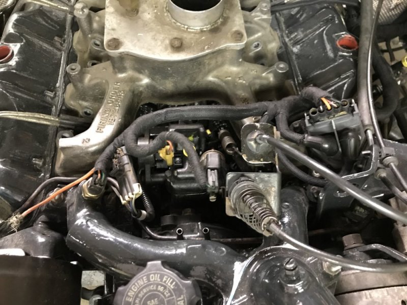
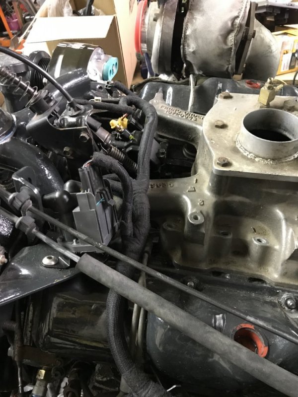
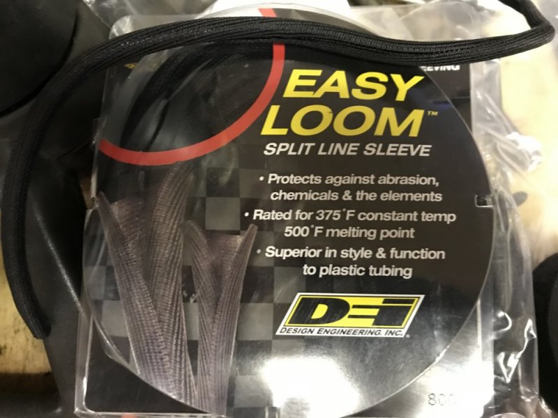
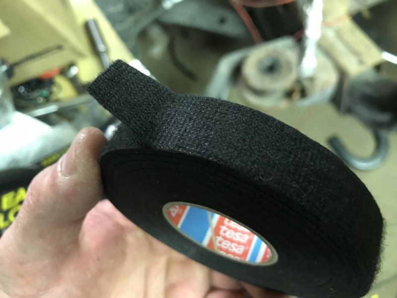
I got the engine side of the harness all loomed. I used DEI Easy Loom and taped all ends and intersections with Tesa tape. The tape is supposedly used in Euro cars. It sticks to itself really nicely and matches the loom nicer than regular electrical tape. It will be interesting to see how it holds up. My brother said he’s seen similar tape on snow plow looms and that it’s good stuff.

214F0761-0782-49A1-BFA6-A8D22068501B.jpeg514BD267-3EC9-483D-80FB-8DDC7BC380D9.jpeg

Overall it turned out well, but I would have done a couple things differently now that I see the finished product so I’ll make those changes when I do Krovvy.

8C0D67C1-D5D7-4C1E-A274-7757C1907130.jpeg5C181BE8-7C3F-430C-BC70-8DDCB5EEFF65.jpeg

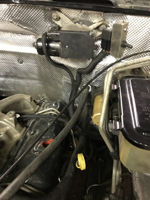
This is one spot I would have done differently - I would have ran the wiring for the wiper motor and the fuel pump relay up and over rather than down to the harness at this point. Mostly just to be cleaner visually. The toggle switch is so I can turn the fuel pump on manually for priming and diagnostics. I wired 4 signals for the lift pump relay and put a diode in each line so there wouldn’t be any backfeeding. The signals are the manual toggle, the cranking circuit, the oil pressure switch for main running and then I also added a trigger from the glow plugs so the pump primes and circulates fuel when the plugs are cycling. May be overkill, but it made sense to do it that way in mah brain.

23AFC8CD-D0E0-4491-998D-567A96AD74FF.jpeg

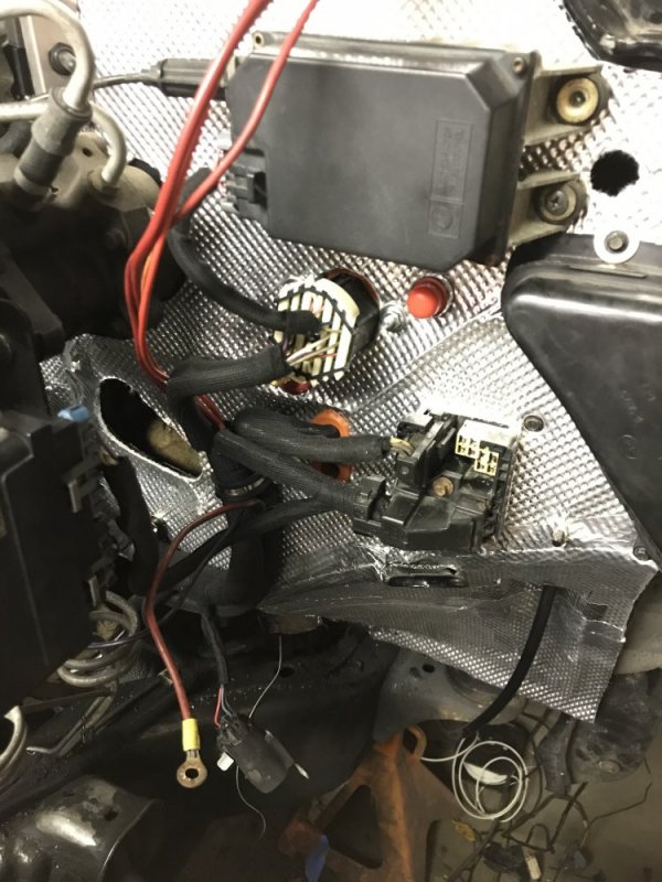
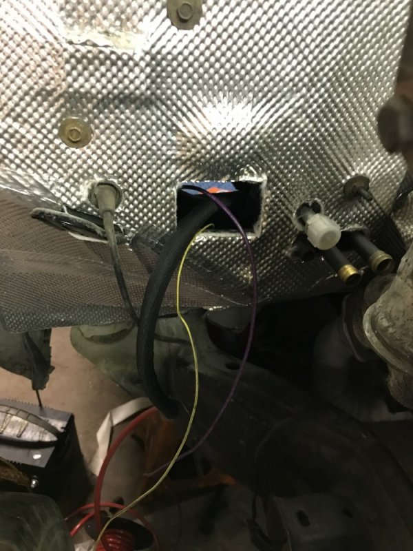
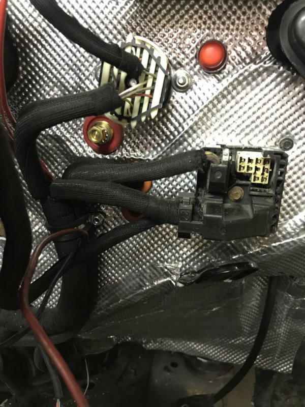
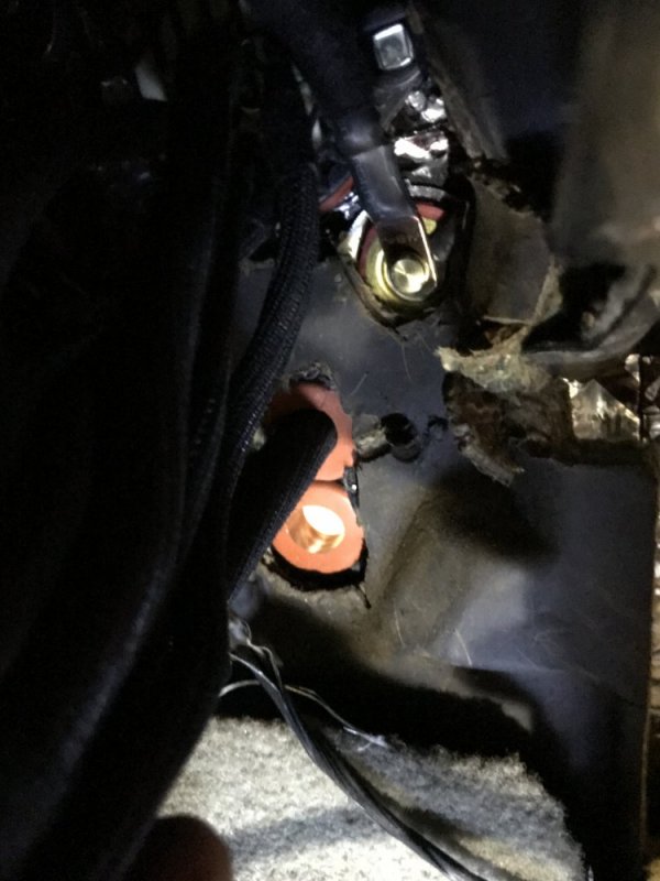
Over here is the finished Weatherpack bulkhead. I also wired in a button for the starter so I can turn the engine over from the firewall side for diagnostics and what-not. I ran the transmission wiring through a grommet. I will also be running lines for gauges and other stuffs through the second grommet. I still have to do the power connections for the main circuits - I’m still planning how I want to do those. I ran a power post through the firewall because my batteries will be under the bed on the passenger side so I ran a 4 gauge wire behind the dash to supply power to the driver side of the truck and still keep the firewall clean.

6AB1C77C-50F9-4C6F-9B8F-442DF56CF365.jpeg

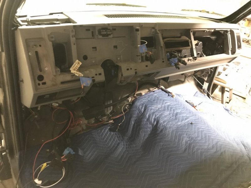
This side needs more work done, but I got enough run so I could get the dash in place.

90C2C8D9-DD56-49C7-AC15-6DC586122B1C.jpeg

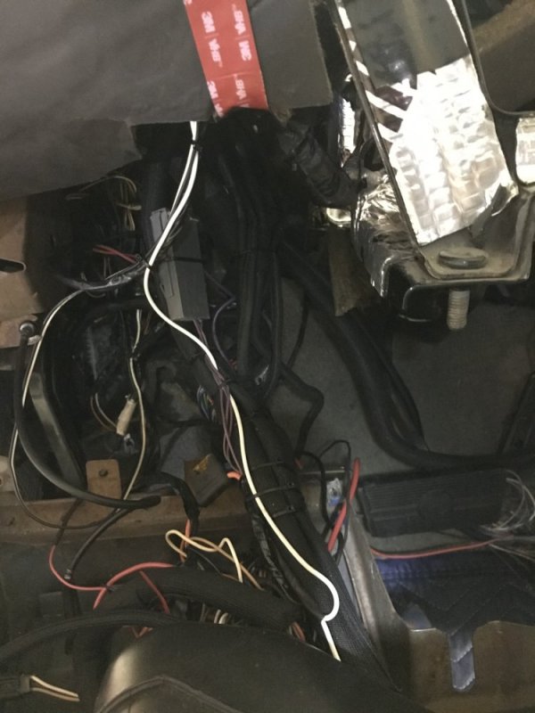
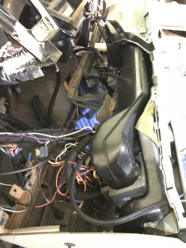
The back side of the dash took a while. I had to locate the circuits I kept and then run those wires to the bulkhead. Then once all of that was done I had to loom it all. I left some of the larger packs of wires a little open both for simplicity and in case I need to do any tracing in the future from underneath.

764DA611-F394-4EEF-8D9E-EA70B92EF682.jpeg01E3233F-398E-4DA0-B281-A534A8B78A5E.jpeg

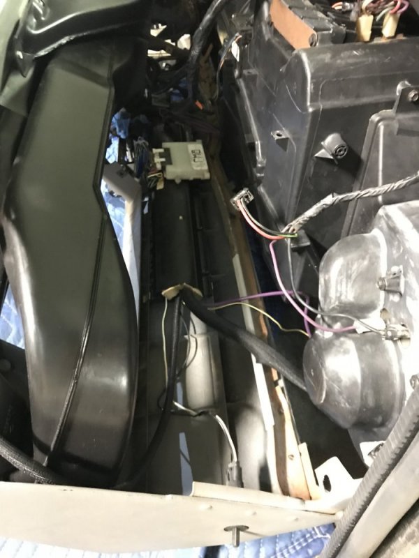
The passenger side is much simpler now that the PCM is gone. I still need to figure out where I’m mounting the US Shift Quick 4 so the trans harnesses aren’t tight with the rest of the wiring.

2604E0C1-1C7D-42B1-A229-8A60210BA79F.jpeg
 
I noticed you couldn’t see the power pass-thru post in the other pic so here’s a better view of it, just below the Weatherpack bulkhead.

5170AF5C-AE8A-40B8-BCF0-805E760F313C.jpeg

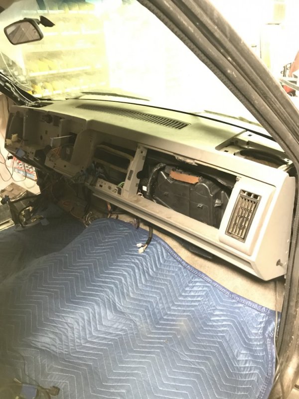
And here it is from inside with the dash rotated up.

01A88C84-5DC3-408A-B87C-3B02E1A7D89E.jpeg

Speaking of.....

57889B3D-0221-47DF-90A6-2AE8E359E6DB.jpeg2B307A55-7643-4E47-91C4-ABF71882CE5D.jpeg

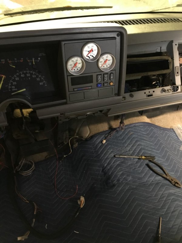
It feels good to have that up in place. For now I just have the two lower bolts holding it up, but it’s enough. Now I can reinstall the steering column and then get my gauges installed.
 
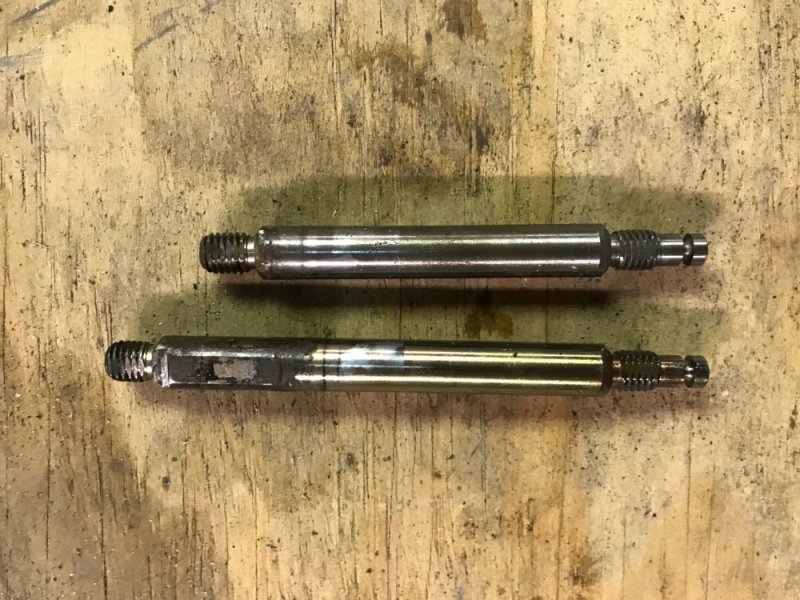
Last week I went to install the transmission linkage so I could check to make sure there wasn't interference between it and the harness. This is when I found out the hard way that the shift shaft in the transmission is a different length between the 94 and 97 transmissions. So last night I took the shift shaft out of the 94 trans to put in the 97 trans. Here are the 2 shafts next to each other, the 97 is on the bottom and the 94 is on the top.

shafts.jpg

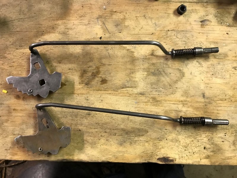
But there was more to it than that. The 94 shaft wouldn't fit in the 97 quadrant in the linkage, so I had to swap that as well. You can't tell in the pics, or even when holding the parts in your hands, but the hole for the shaft in the 94 (bottom) is larger than the one in the 97 (top), so I had to swap this as well.

linkage.jpg

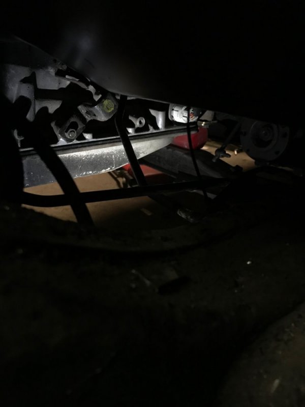
I got everything swapped and the trans pan reinstalled, then got the linkage installed. I haven't replaced my phone yet, so I still can't take pictures above horizontal, so the only shot I could get was this creeper pic from the wheelwell.

installed.jpg
 
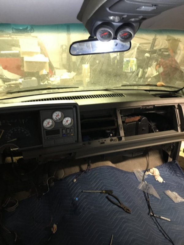
Got some more stuff done: gauges are installed.

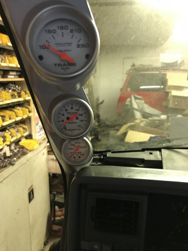
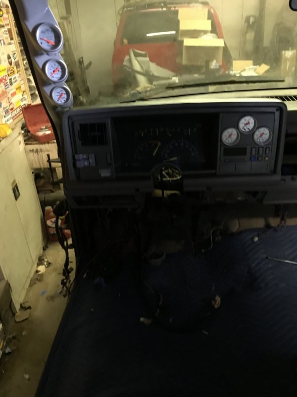
Earlier this week, I got the temp gauges installed in the pillar pod. Trans Temp, Pyrometer and mechanical Water Temperature.

5FEFD3BA-1E7C-4BF2-A39C-D7EFFC248DA7.jpeg

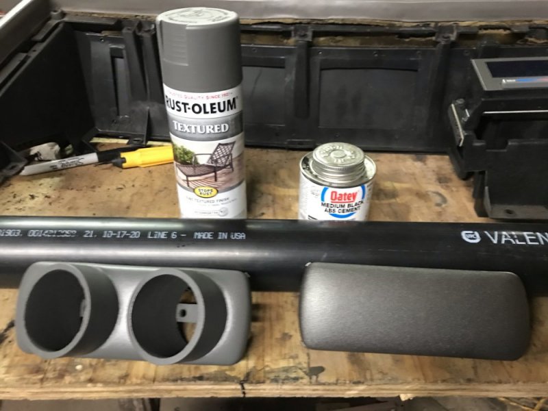
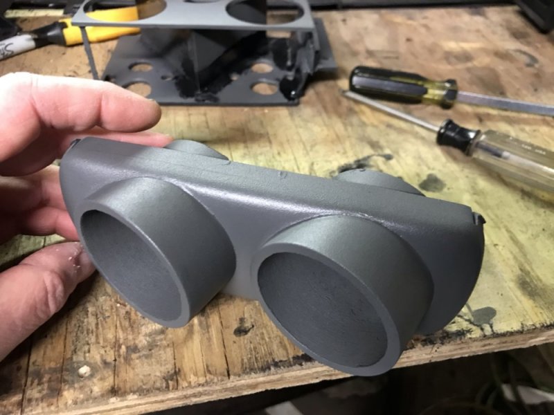
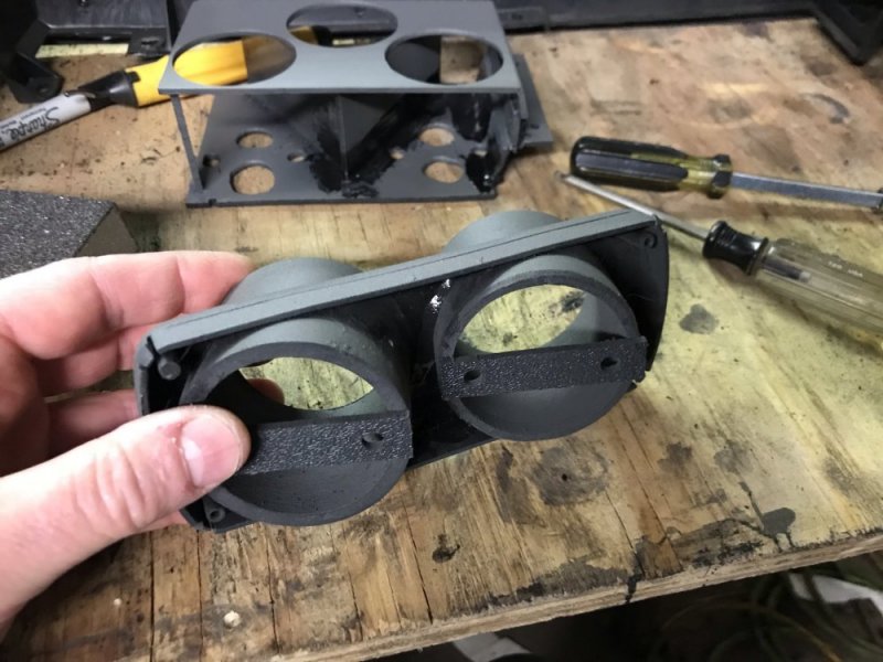
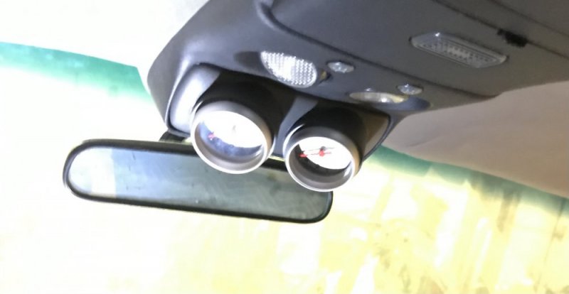
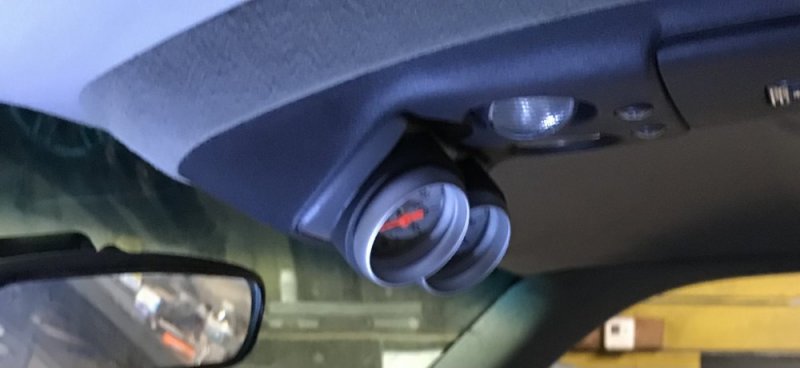
Last night I got the Drive Pressure and Boost gauges installed in the overhead console. I made a pod that started with a factory blank panel (it already had a hole cut in it, so I didn’t cut up a rare-ish part). I got some ABS pipe and after cutting them to length I glued them to the panel to make the pod. I’m still having phone problems, so I can’t take great pics. I’m planning to get a new phone over Christmas break.

64A9CA51-074D-4A83-ABF9-757BCB3B6339.jpeg04FAC72F-1C53-43EE-A996-E8ED4293DF31.jpegB5756602-2DC2-4288-8DDA-692585CE5388.jpeg9AB6A2CF-4D0B-42B8-A50A-F0FF37BD180C.jpeg9D1FF067-3D4A-4F5E-A9E0-F0F45D3F665D.jpeg
 
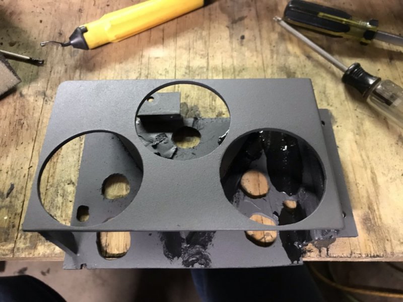
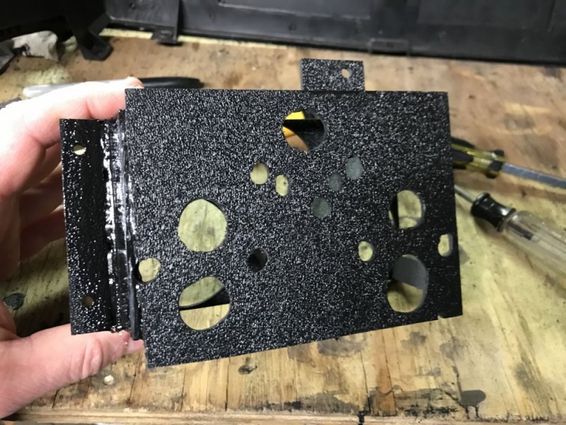
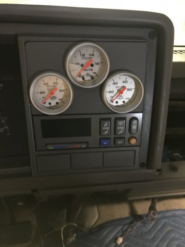
Then tonight I got the dash mostly assembled including the pod I made to replace the radio head. This pod houses my Volt Meter, mechanical Oil Pressure and mechanical Fuel Pressure (yes, I’m running an isolator). I still have to plumb the gauges, so I will have to pull some of this back apart, but I was excited to see it all together. I’m pretty happy with the results. The back side isn’t pretty because I was figuring it out as I went and didn’t feel like making it over, but the front side turned out well (after a second attempt) and that’s the side that counts.

FA7CBBC3-409B-4DAF-A14C-6AD3FFB4FC8B.jpegF41895B5-4E34-4275-8DC0-20AE84A0C4FD.jpeg5C7D8822-AB3E-4065-90B0-5C5AD5AB97C7.jpeg1F795229-ABA5-427C-A42C-21D0B9736DF9.jpeg08179E17-E197-49B5-B642-0900A3E691E9.jpeg716CD72C-6E5A-4EB2-8E05-405AA808A9A0.jpeg
 
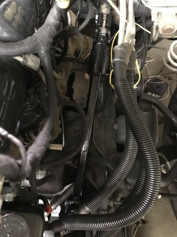
I’ve been working on the fuel system lately and it’s been taking some time to plan and execute. In the meantime I ran to the junkyard to get an XJ steering shaft so I could eliminate the rag joint. They didn’t have any 94 and older XJs, but I did find one early model year 95 that had the right shaft so that was lucky. I cleaned it up and slapped some KBS on it and now it’s installed (after the normal mods to do this conversion). So now for the first time in months I can steer the truck with the steering wheel once again.

730041E1-BB99-4D1E-9CD3-6ACADA1A572A.jpegF9A25371-05ED-4770-9F3F-B09C7FA01AF8.jpeg
 
Finally have some more progress to report. Between the holidays, some other small projects popping up and then the motor on my air compressor taking a crap, I haven’t gotten nearly as much done as I have hoped to over the Christmas break.

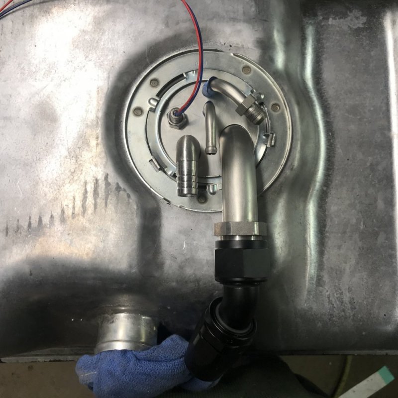
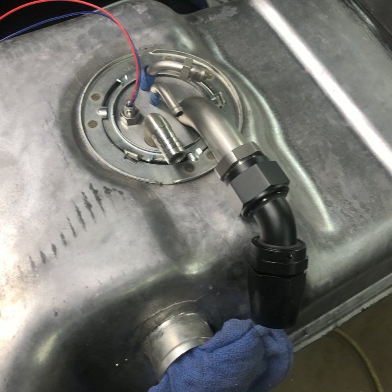
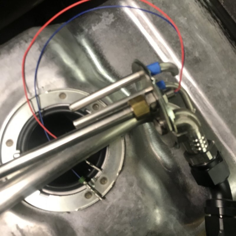
First thing I was able to accomplish is to get my fuel sending unit mocked up. For a couple years I’ve been wanting to try a 1” draw straw in addition to an external, return-style fuel pressure regulator to see if that would help the Raptor 100 lift pump to keep up with the Tahoe’s IP. Since pretty much everything from the Tahoe is going on this truck it seemed like a good time to try it out. I started out just trying to add the 1” tube to a stock FSU by moving a tube or two around......that didn’t work. The tubes were attached to the plate by brazing and I wasn’t able to get the tubes removed cleanly and then not have braze left over that would contaminate the welds later, so I scrapped that approach. Clean slate it was then. I got some 14 gauge stainless sheet and cut out a new plate. After that I started making holes for the various tubes and then the Leroy Metrum Rod. It turned out pretty well. What I have here is a 1” OD supply line, 3/8” OD fuel pressure regulator return, 5/16” OD IP/injector return and a 5/8” OD fuel tank vent. I’m still waiting for my filler rod to show up so I can weld it all together, so it’s still just in the mock-up state.

006B25AD-6738-4D65-98B4-AA70A1E78655.jpeg8C6671CF-DB11-4A00-82ED-DA70DB97D104.jpegAB00A2E8-A775-41A2-9180-B80B0BFF76D2.jpeg

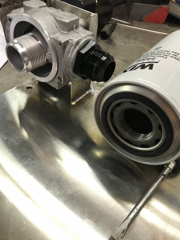
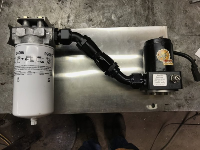
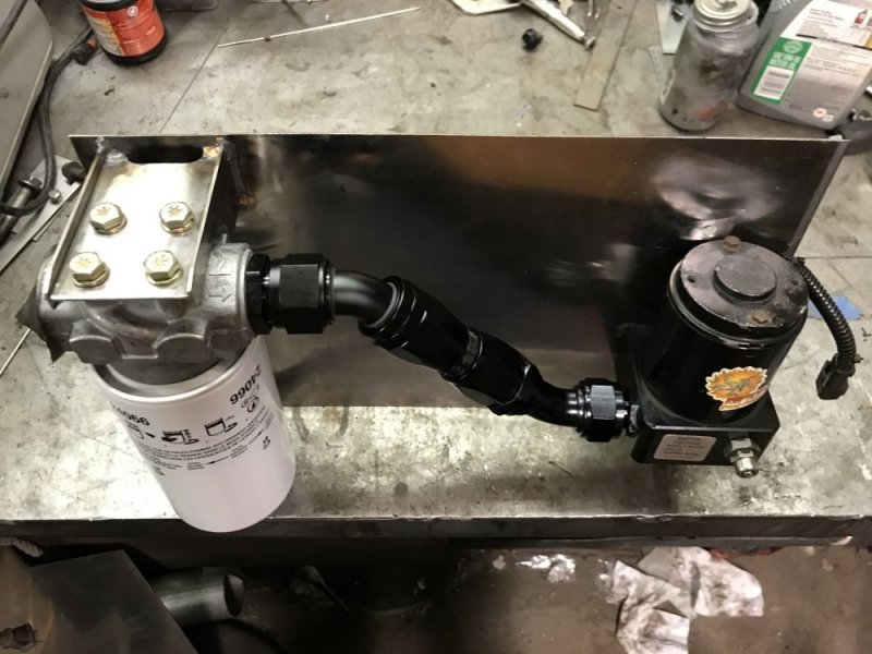
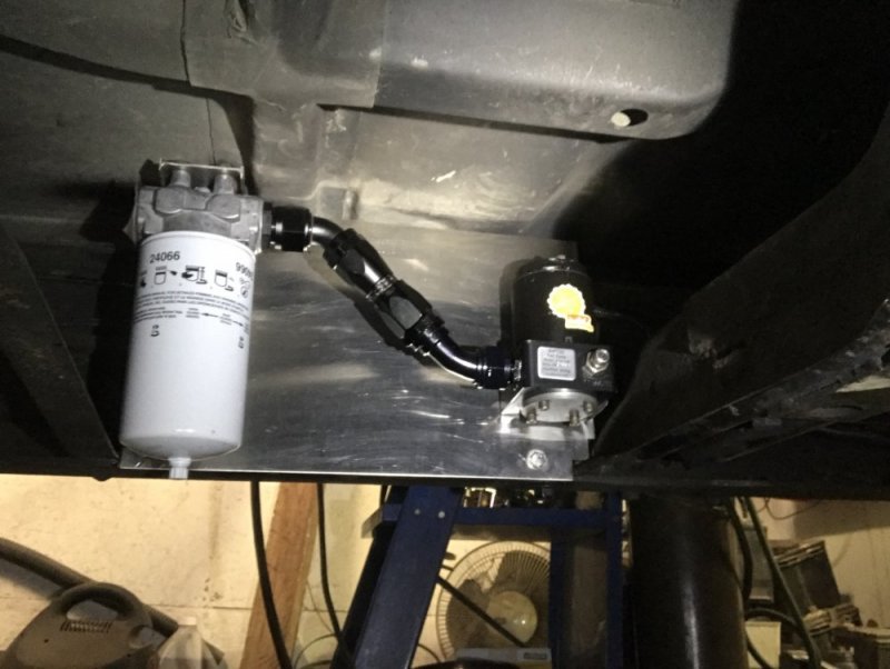
After that I moved on to a plate for mounting my pre-filter and lift pump. I wanted the whole fuel system before the lift pump to be 1” so I searched for a new filter base with those specs. I found a Donaldson P164667 base with -16AN inlet and outlet and a 1-3/8” filter thread that fit the bill. Then I got the -16AN hose and all the fittings to make it work. Since I had the 14 gauge stainless sheet I figured this was a perfect time to finally use the TIG welder I bought fall of 2019 and still haven’t used. In hindsight I should have done something simpler. I don’t have a lot of TIG experience and what I do have was on carbon steel 1/8” and thicker, and that was like 10 years ago......turns out jumping back in the saddle on thin stainless with a machine and consumables I’m not familiar with wasn’t the best idea. I ruined my first attempt at the filter mount and had to start over. I changed my approach and ended up with a usable piece, but it isn’t nearly as nice as I hoped it would be, luckily it’s just a part mostly hidden under the truck. It was good experience though and I need to do some more TIG projects so I can get better. I was thinking I’d be making some more stuff for under the hood with the stainless and TIG, but now I think I’ll change my approach so I can get it done more quickly and also to a finish level I’m happy with.

76D16CD8-6614-4DD7-A0BD-F560DD3148DE.jpeg4B70C9EE-E624-40BF-8E85-9FDFAEE4F8A4.jpeg4B826564-BB3E-426C-85FE-2ECFD53AF37A.jpeg79B93B41-C32B-47C5-A6CE-38EB29B0D52B.jpeg

Yes, this is probably overkill, but also I think it’s a cool experiment: technically the Raptor 100 should have had enough output to keep up with the Omega Moose IP at 25psi inlet pressure, but it would drop to 16psi at full throttle. If good fuel and hydraulic theory prove out, it should be able to keep up now and do so more efficiently and also put less heat into the fuel at the same time. We’ll see if that proves out.

Oh and Happy New Year, good riddance 2020.
 
Looks real nice!

I like the large suction tube approach. That is something I was told by a engine tuner a while back in reference to superchargers. They have no issues pushing through a distance of tube, but they don't like to suck through a small, long tube.

You may want to consider running your regulator return line to the bottom of the tank, or close to it. Fuel dropping in will create air in the fuel. Your large suction tube will pick up all the air bubbles.

You may have already thought of all this since you are showing us a mock up.
Good eye, Duvall. Those return lines that are shown are just the beginning. Those stubs are there to attach a short piece of 30r10 submergible rubber hose and then there will be a long straight section of tubing attached to that. The goal is to have the return dump closer to the rear of the tank, away from the pickup tube - my thought there is that the pickup wouldn’t pick up any air that may have been returned, there would be less turbulence around the pickup and also the fuel that had been heated from pumping and running through the IP and injectors would be further from the pickup so I’d be sending the coolest fuel in the tank to the IP.
 
In tank baffling was the old method for continuous flow tanks to help keep aerated fuel from getting to the pump. If it were a homemade tank- you basically build channels for the fuel to flow through. Not really practical with this tank, but incase you ever get the itch... But adding line to the return to get it far away as possible is a good idea.
But still nothing gets it out as good as the airdogg or fass extra return line systems.
 
Good eye, Duvall. Those return lines that are shown are just the beginning. Those stubs are there to attach a short piece of 30r10 submergible rubber hose and then there will be a long straight section of tubing attached to that. The goal is to have the return dump closer to the rear of the tank, away from the pickup tube - my thought there is that the pickup wouldn’t pick up any air that may have been returned, there would be less turbulence around the pickup and also the fuel that had been heated from pumping and running through the IP and injectors would be further from the pickup so I’d be sending the coolest fuel in the tank to the IP.

You have motivated me to get moving on my fuel system as well. I peeked under my truck yesterday and forgot how far forward the lift pump is from the fuel tank. Interesting position considering gasoline applications are close to the tank if not in the tank. (And yes I remember the days of the diaphragm pumps mounted to the engine block.)

So another thing to consider is to move your lift pump as close to the tank as you can. This will limit the amount of 1" pipe or hose you need to run and help reduce the suction for the pump. You probably already thought of this as well. :p
 
Thats a big reason why many cars are adding a sump to their tank and having the fuel pump driven as close to that point as possible.
And in almost every (maybe every) modern made vehicle that is running an electric pump has the pump in the tank. It’s called a pump because it pumps, it is not called a suck.

Gmt400 gas pickups already had fuel pumps in the tanks. They biggest problem with in tank for diesel but jelling - they couldn’t solve it. Beyond that, diesel being thicker and heavier means the pump works harder and would wear out sooner. So fighting those two issues under warranty wasn’t worth the risk.
 
You have motivated me to get moving on my fuel system as well.

So another thing to consider is to move your lift pump as close to the tank as you can. This will limit the amount of 1" pipe or hose you need to run and help reduce the suction for the pump. You probably already thought of this as well. :p

I’m sorry about the motivation. 😅

Where I have the pump is the closest I could get it to the fuel pickup and keep it on the inside of the frame rail. I suppose I could have gotten it closer if I had put it on the outside of the frame rail, but I don’t want all of that business on the outside of the frame both for looks and for protection, which reminds me......I still need to make a skid plate for under the filter.

It’s called a pump because it pumps, it is not called a suck.

Are you sure about that? We sure seem to get a lot of pumps that certainly suck 🤪.....hence us looking for pumps that flow on fail.
 
Blew a fuse on my raptor sometime recently, not exactly sure when. Turns out the raptor is at least somewhat flow on fail. I noticed when I pulled out on the highway this morning it stumbled pretty good and looked at my fpg and it was sitting on 0. Turned around and drove back home and put a new fuse in it without shutting it off
 
Back
Top