SnowDrift
Ultra Conservative. ULTRA!
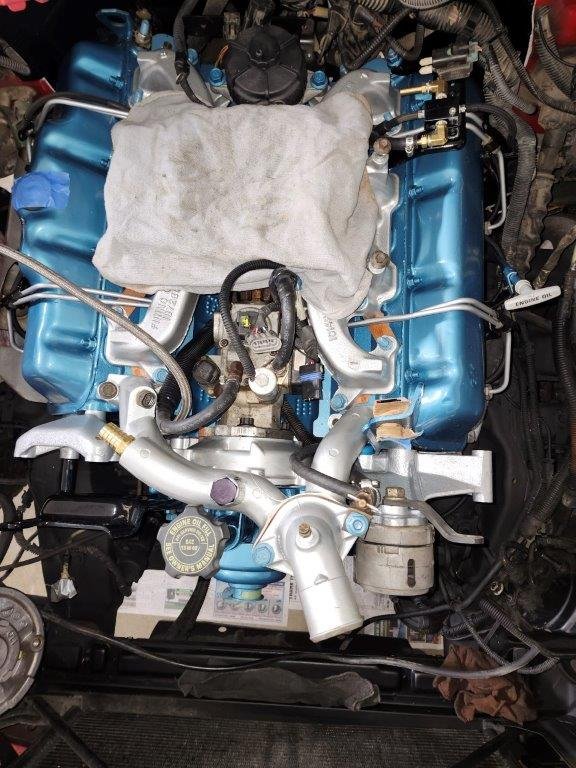
This was in a bag of hardware I had labeled for the intake manifold, but I can't identify the bracket or what it holds. Any ideas?


Follow along with the video below to see how to install our site as a web app on your home screen.
Note: This feature may not be available in some browsers.


'95What year? Depending on year, maybe a throttle cable?

1st postWhat bracket?