
496 BB
Gasoline Enthusiast
Ok here it is finally. This can be reference to just replace the standard bulbs in the switches also. It includes the drivers and passenger side front and rear switches. 4x4 switch is in separate thread.
Items needed:
- (4) 5mm LEDs
- (3) 3mm LEDs
- (7) Resistors
- Soldering gun and solder
- Small screwdriver (jewelers is ideal)
- Star bits (for removing switches from door panel)
First off all lets talk resistors. What I use is not necessarily going to be the ones you use unless you are using the same exact LED. Its all based upon forward voltage (voltage going across the die inside the LED) and the forward current. Forward current is usually 20mA for 3mm and 5mm LEDs. However the forward voltage differs depending on the color of the LED. Easy to figure this out. Where ever you order em from just make sure you get the specs of these two items and plug it into this calculator. For my build I used something not recommended because I want to see how they last with more power. Its a long complicated story as to why and Im not going into it..lol. So far they have lasted over a year with em. I would have used the 560 ohm 1/2W resistor as I tend to use 12.5V as the voltage going thruout the truck.
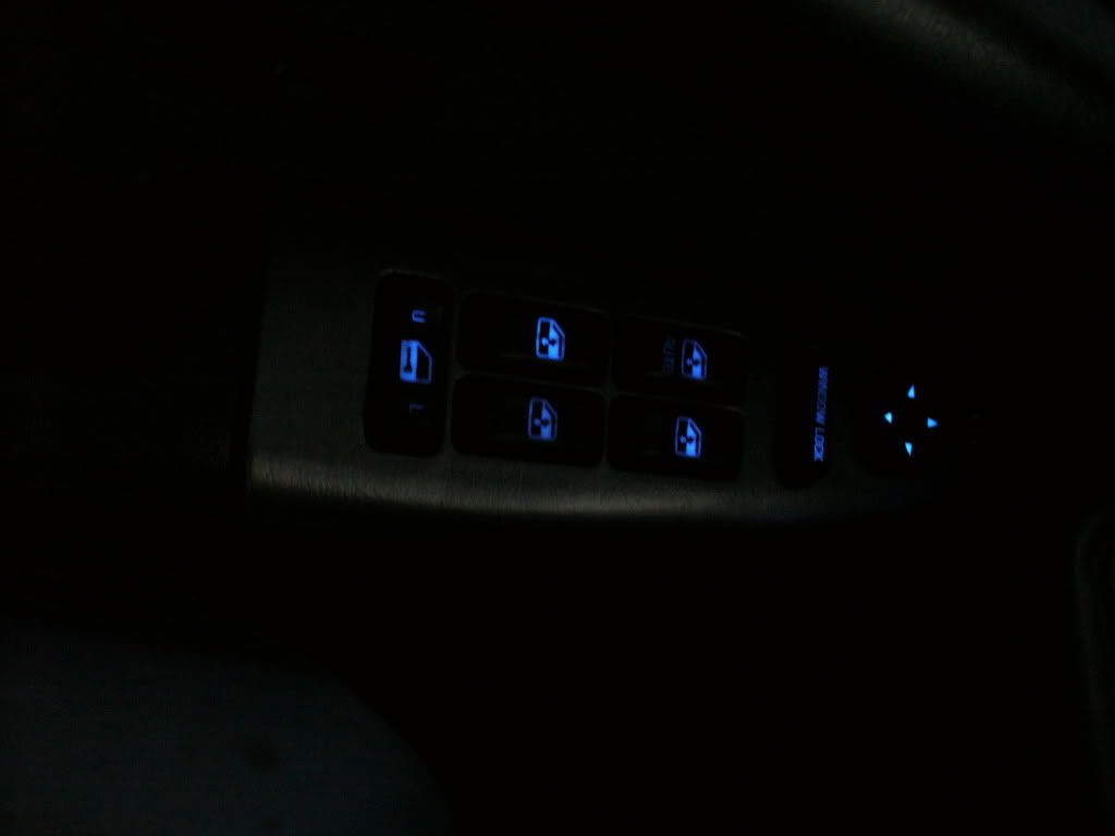
Now for the LEDs themself. LEDs are polarity sensitive meaning they will only light when the + and - are correctly applied. Each LED will come with two legs. The longer one is the anthode which is the +. The shorter leg is the cathode which is the -. LEDs have varying viewing angles that can really make a difference in where you place them. Also the different viewing angles can also produce different shades within the same color spectrum. For example....a 45* viewing angle Blue bulb produces 470nm (wavelength) and a 360* viewing angle produces a 462nm. While this is not significant it can be slightly noticed. Also these two bulbs vary greatly in actual light output. The smaller the viewing angle typically the brighter but more focused. For this reason I use 360* bulbs in everything. They provide the scattering of the light I need/want and I never have to worry about "Hot spots" in areas. They are not as bright as some of the dashes youve seen on here but I dont want that anyways. I like subtle. They are not dim by any means but they light everything uniformly. These are goor especially since alot of these switches have "light bars" inside them that distribute the light from one point to another thru an acrylic clear runner.
Ok on to the fun stuff....
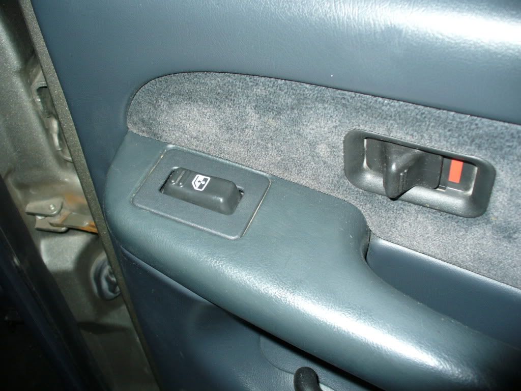
Rear crew cab window switch
- Take door panel off. (2) 7mm screws...one at armrest underneath and one at bottom of door. Be careful not to pull out all way until you remove the 194 bulb in the reflector part. Remove switch by popping the top cover up carefully.
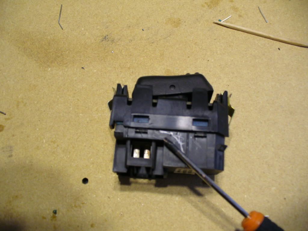
- Take switch apart by using small screwdriver and prying apart the cases at the tabs
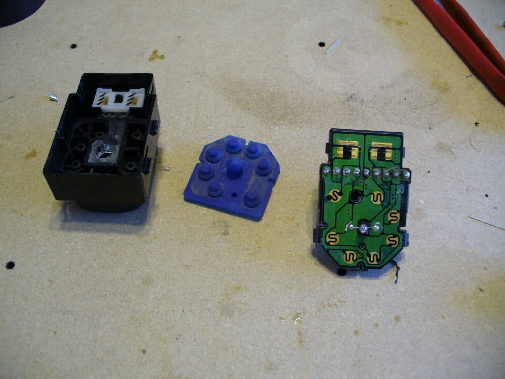
Now pull out the circuit board and take the blue rubber off. Dont loose the 2 white plastic tabs in there.
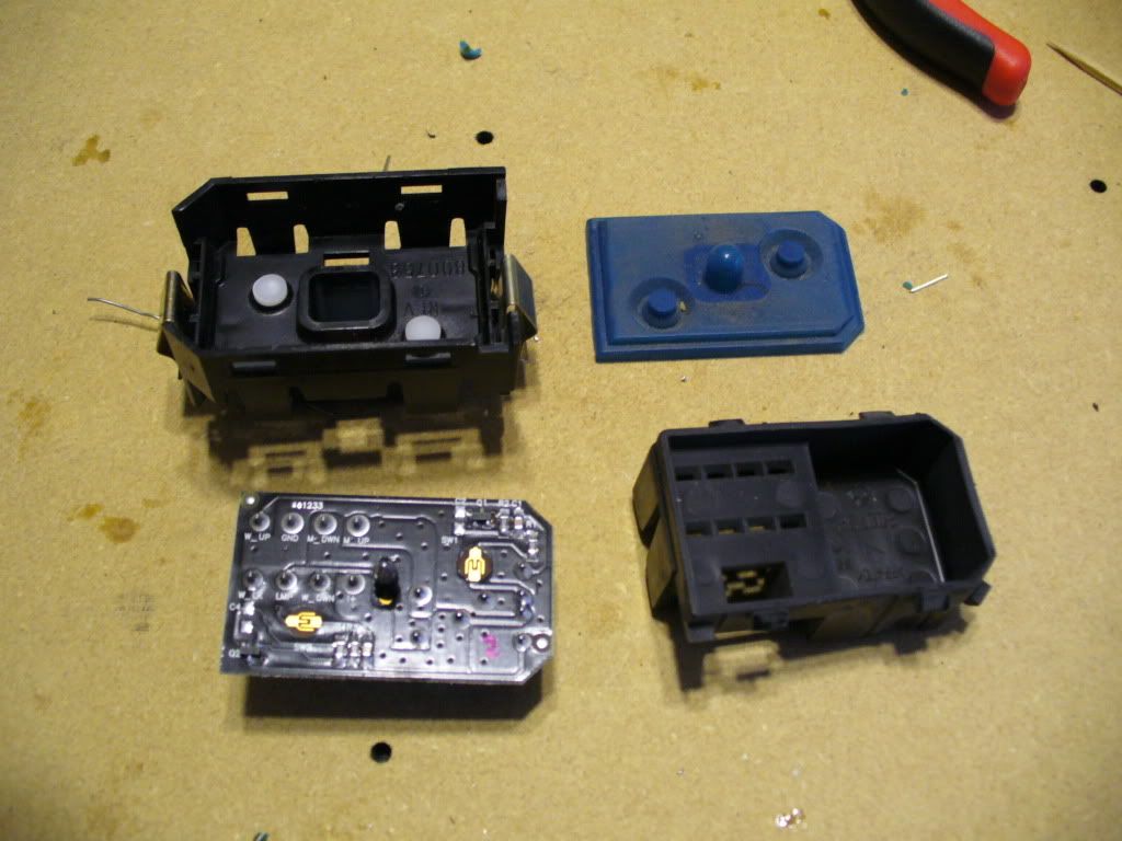
Ok. Now you can see the bulb in the center. This switch takes a 3mm LED. Heat the bulb ends up on the oppisite side as to not apply alot of heat. I pull to the opposite side of where Im heating up and do one side at a time. Once you get the bulb out you need to find the + and - on the circuit board. I made a "test" LED with resistor and just use it when I plug the switch back into the harness in the truck and find out what positive and negative is on the board and remember it.
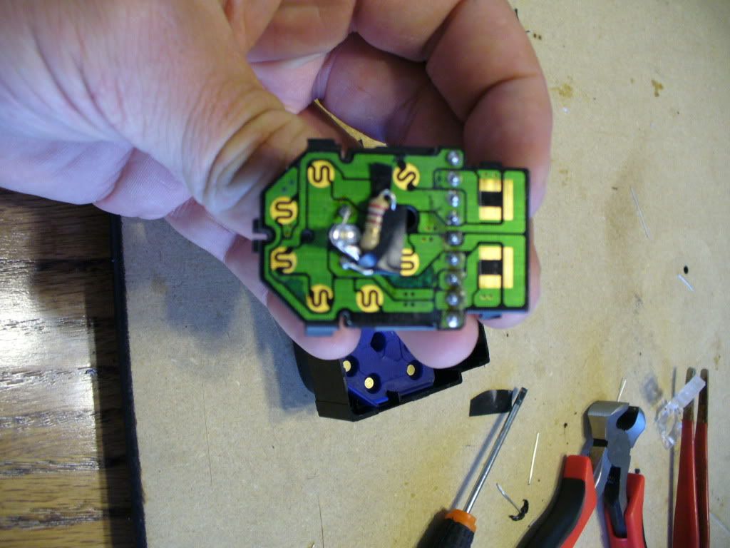
Now make a mental note of how you want to lay out your LED and resistor as to not interfere with any of the switch's function. Once you do this put your resistor in the positive side hole (you may have to heat up briefly to get it in and solder out of way). Dont have to solder in all the way yet. Now put the negative side of the LED in the remaining hole. Dont solder in all way. Now conjoin the positive of LED and the resistor by soldering. I like to this off the circuit board as its easier. What you did until now was mocking it up. Once you get it where you want then you can solder everything in for good. Just make sure your not touching any wires from the LED or resistor to the circuit board causing a short nor having the + and - side of the LED and resistor touching each other.
This was BEFORE I moved the resistor to the left pointing up and down. I suggest to do that
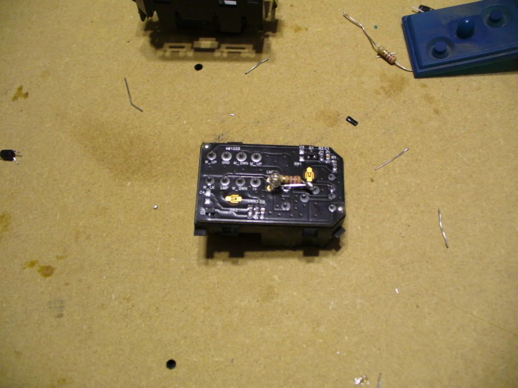
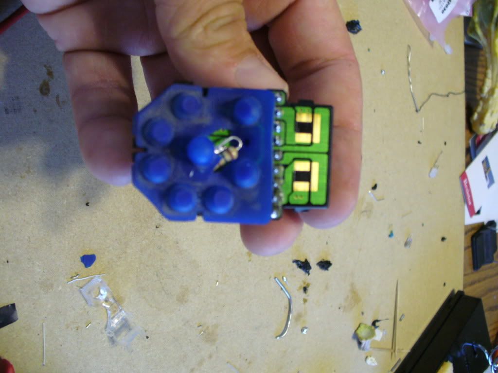
When your done with that go ahead and test it out in the truck to make sure it functions correctly. If it does then carefully put the rubber back on and fit in casing gently as to not smash anything. It will be tight but it works. Now go test it again to make sure you didnt smash anything. If you didnt then you are good to go!
Driver Side Door Switches and Locks
Remove switch assembly by pulling up and out on the whole section. It comes out with a trim piece. Disconnect wiring harness.
Remove 2 star bit screws and slide out towards end and up to remove switches from panel. Pry out mirror switch with small screwdriver where the tabs are.
Now once you have that separated take the buttons off the window and lock switch. To do this use the small screwdriver and go in on an angle where it pivots on the side. Gently pry upwards. Either way they just pop off. Take all off. Now go ahead and split the cases like before. They have tabs on sides and top and bottom...just work your way around with small screwdriver.
Now you can see the (2) lights. One on top and one on bottom. Go ahead and gently take off the clear acrylic light diffusers. Set aside. Now on these you have to reference where the bulb is on the back side in relation to the from side and make a hole the size of a nickel in the back of the housing. I used the soldering gun to make this hole by melting the plastic and being careful not touch the circuit board inside. Do this for each bulb. The reason for this is the whole circuit board is soldered in from the factory with the pins already cast into the housing. Either do it this way or heat up every pin at same time remove it that way.....not gonna happen. Now you should be able to see the (2) little bulb ends soldered into the back of the circuit board.
Now go ahead and unsolder the bulbs. May have to do from top and bottom. After you get em out go use your test LED and find out + and - and make note of it. The rest is the same as above. These are 5mm LEDs. These also are tricky in the sense that you have to fit both the LED AND the resistor inside the opening on the clear diffuser. I ran my resistor up and doubled it back down and connected it to the LED so they are sandwiched side by side. Because of this I had to use electrical tape on one side so it didnt touch the - side. I would imagine it would be easier to use liquid electrical tape but didnt have any nor have I tried it. You choose. Also make sure the LED DOES NOT exceed the height of the diffuser. Do your mock up first then solder it all in. Make sure you test fit the diffuser after you test it for light up.
Height....
These are tricky so be patient and take your time with it. Once everything is lit and good go ahead and put the switch back together and put buttons back on by snapping em in place. Test again.
Power Mirror Switch
Split the cases by prying the tabs. Now remove the blue rubber. Make sure you keep tabs on the white tabs that like to fall out.
Now you can see the bulb. These are surface mount solders so you can unsolder it from the top. Briefly touch the solder points to get bulb out. Go use your test LED and find out + and -. This is a 3mm LED. Now this is a tricky switch. NO ROOM. You have to mock this really carefully cause you have contact points all over as you can see. Its like a snake when its done. Just make sure you use tape or liquid tape to cover areas prone to being smashed a bit on the circuit board when the cover gets put on so there is NO metal to metal contact causing a short.
Now once you get everything soldered in go ahead and test the bulb out. If OK then test fit the blue rubber and make the necessary relief cuts in it not cutting into any of the humps or contact points. Dont worry about the center one as its just for the bulb and diffuses light since 3mm you cannot get in 360* viewing angles.
Now this is a tight fit when you put the cases back together. Go ahead and do it gently and try to be careful. It there is resistance then adjust it accordingly. Test it out once its back together and YOU ARE DONE....with this one side.....
Now you can do this in regular incandescent bulbs also like it came with or with any color LED you want or can find. Im sure Ill be adding to this as I keep looking at it but it took forever to write this and its supper time
ENJOY!
Items needed:
- (4) 5mm LEDs
- (3) 3mm LEDs
- (7) Resistors
- Soldering gun and solder
- Small screwdriver (jewelers is ideal)
- Star bits (for removing switches from door panel)
First off all lets talk resistors. What I use is not necessarily going to be the ones you use unless you are using the same exact LED. Its all based upon forward voltage (voltage going across the die inside the LED) and the forward current. Forward current is usually 20mA for 3mm and 5mm LEDs. However the forward voltage differs depending on the color of the LED. Easy to figure this out. Where ever you order em from just make sure you get the specs of these two items and plug it into this calculator. For my build I used something not recommended because I want to see how they last with more power. Its a long complicated story as to why and Im not going into it..lol. So far they have lasted over a year with em. I would have used the 560 ohm 1/2W resistor as I tend to use 12.5V as the voltage going thruout the truck.
Now for the LEDs themself. LEDs are polarity sensitive meaning they will only light when the + and - are correctly applied. Each LED will come with two legs. The longer one is the anthode which is the +. The shorter leg is the cathode which is the -. LEDs have varying viewing angles that can really make a difference in where you place them. Also the different viewing angles can also produce different shades within the same color spectrum. For example....a 45* viewing angle Blue bulb produces 470nm (wavelength) and a 360* viewing angle produces a 462nm. While this is not significant it can be slightly noticed. Also these two bulbs vary greatly in actual light output. The smaller the viewing angle typically the brighter but more focused. For this reason I use 360* bulbs in everything. They provide the scattering of the light I need/want and I never have to worry about "Hot spots" in areas. They are not as bright as some of the dashes youve seen on here but I dont want that anyways. I like subtle. They are not dim by any means but they light everything uniformly. These are goor especially since alot of these switches have "light bars" inside them that distribute the light from one point to another thru an acrylic clear runner.
Ok on to the fun stuff....
Rear crew cab window switch
- Take door panel off. (2) 7mm screws...one at armrest underneath and one at bottom of door. Be careful not to pull out all way until you remove the 194 bulb in the reflector part. Remove switch by popping the top cover up carefully.
- Take switch apart by using small screwdriver and prying apart the cases at the tabs
Now pull out the circuit board and take the blue rubber off. Dont loose the 2 white plastic tabs in there.
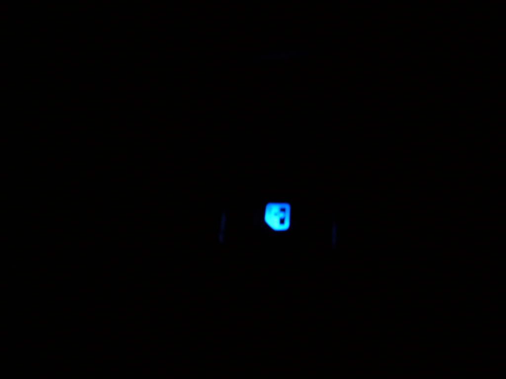
Ok. Now you can see the bulb in the center. This switch takes a 3mm LED. Heat the bulb ends up on the oppisite side as to not apply alot of heat. I pull to the opposite side of where Im heating up and do one side at a time. Once you get the bulb out you need to find the + and - on the circuit board. I made a "test" LED with resistor and just use it when I plug the switch back into the harness in the truck and find out what positive and negative is on the board and remember it.
Now make a mental note of how you want to lay out your LED and resistor as to not interfere with any of the switch's function. Once you do this put your resistor in the positive side hole (you may have to heat up briefly to get it in and solder out of way). Dont have to solder in all the way yet. Now put the negative side of the LED in the remaining hole. Dont solder in all way. Now conjoin the positive of LED and the resistor by soldering. I like to this off the circuit board as its easier. What you did until now was mocking it up. Once you get it where you want then you can solder everything in for good. Just make sure your not touching any wires from the LED or resistor to the circuit board causing a short nor having the + and - side of the LED and resistor touching each other.
This was BEFORE I moved the resistor to the left pointing up and down. I suggest to do that
When your done with that go ahead and test it out in the truck to make sure it functions correctly. If it does then carefully put the rubber back on and fit in casing gently as to not smash anything. It will be tight but it works. Now go test it again to make sure you didnt smash anything. If you didnt then you are good to go!
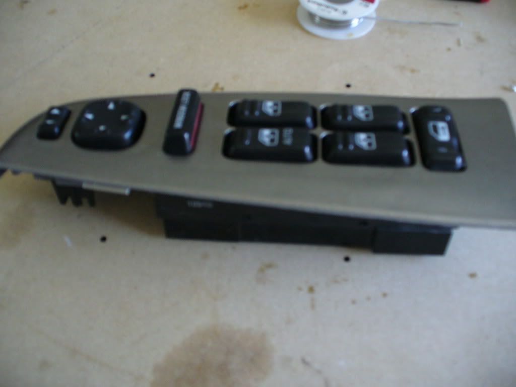
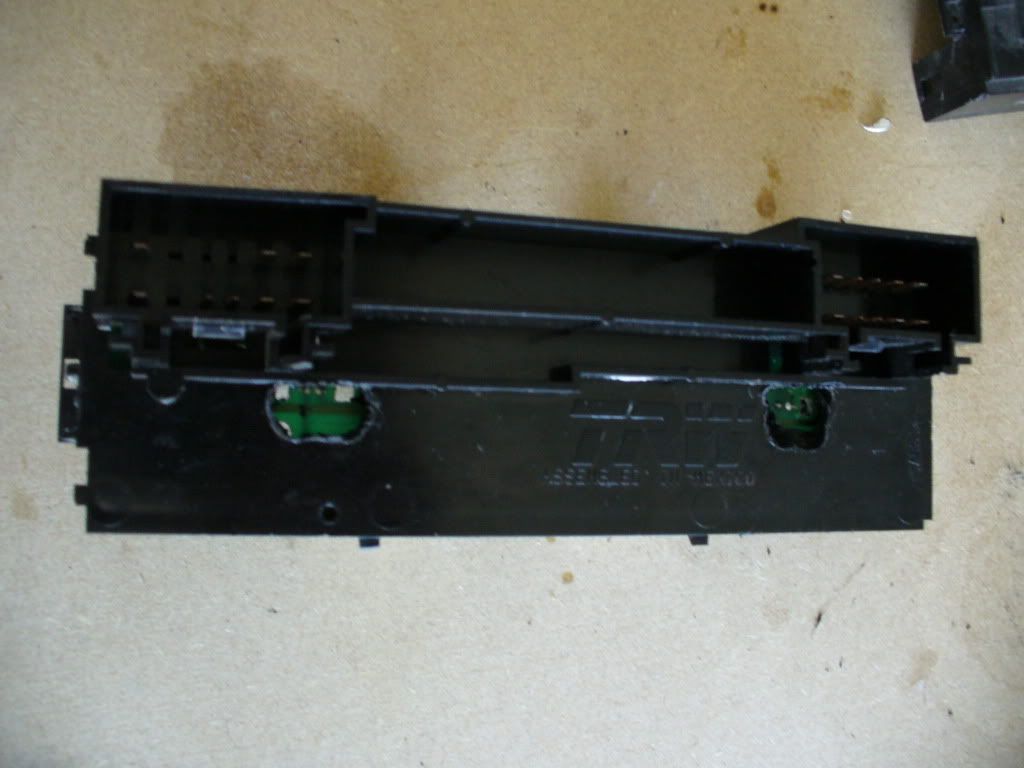
Driver Side Door Switches and Locks
Remove switch assembly by pulling up and out on the whole section. It comes out with a trim piece. Disconnect wiring harness.
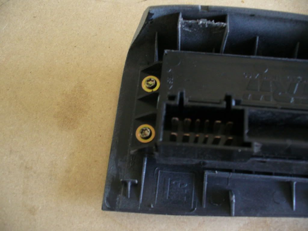
Remove 2 star bit screws and slide out towards end and up to remove switches from panel. Pry out mirror switch with small screwdriver where the tabs are.
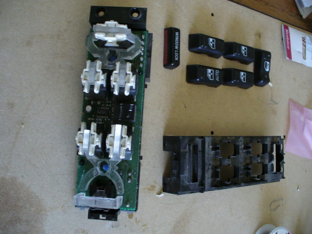
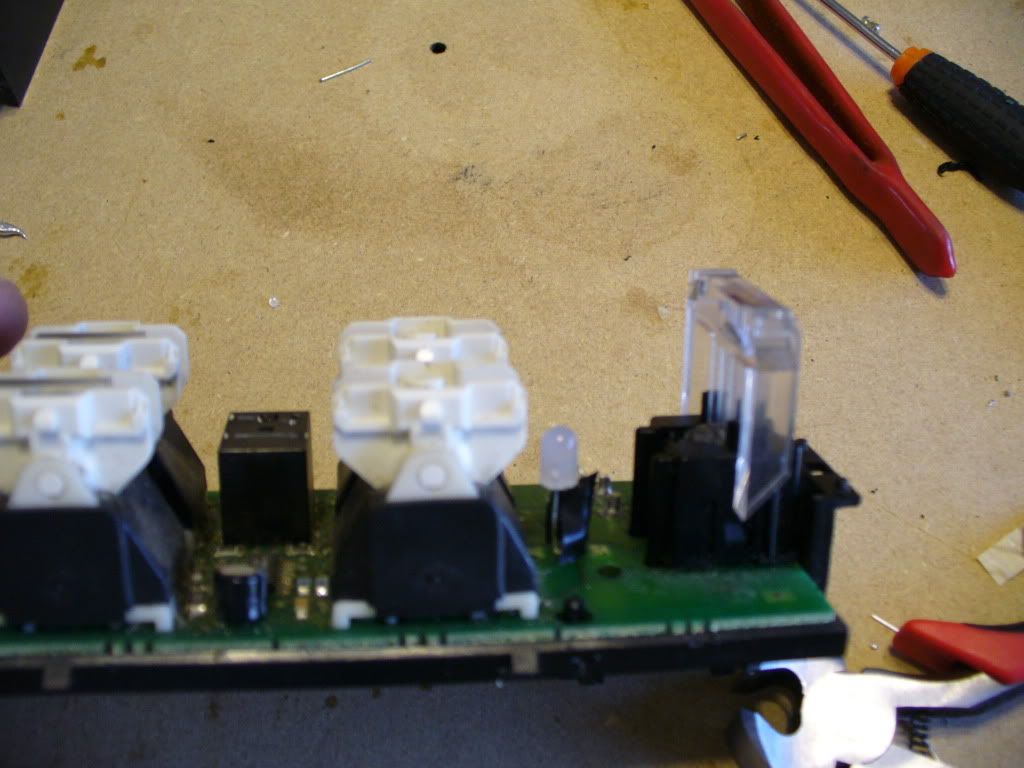
Now once you have that separated take the buttons off the window and lock switch. To do this use the small screwdriver and go in on an angle where it pivots on the side. Gently pry upwards. Either way they just pop off. Take all off. Now go ahead and split the cases like before. They have tabs on sides and top and bottom...just work your way around with small screwdriver.
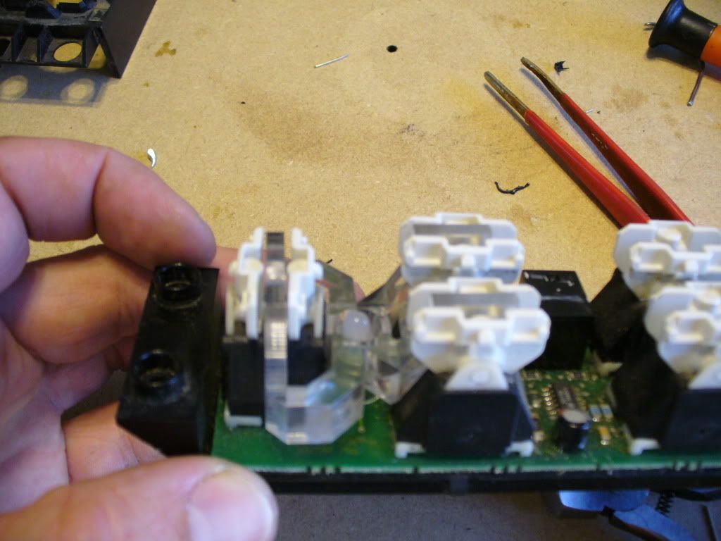
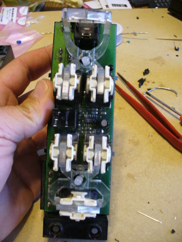
Now you can see the (2) lights. One on top and one on bottom. Go ahead and gently take off the clear acrylic light diffusers. Set aside. Now on these you have to reference where the bulb is on the back side in relation to the from side and make a hole the size of a nickel in the back of the housing. I used the soldering gun to make this hole by melting the plastic and being careful not touch the circuit board inside. Do this for each bulb. The reason for this is the whole circuit board is soldered in from the factory with the pins already cast into the housing. Either do it this way or heat up every pin at same time remove it that way.....not gonna happen. Now you should be able to see the (2) little bulb ends soldered into the back of the circuit board.
Now go ahead and unsolder the bulbs. May have to do from top and bottom. After you get em out go use your test LED and find out + and - and make note of it. The rest is the same as above. These are 5mm LEDs. These also are tricky in the sense that you have to fit both the LED AND the resistor inside the opening on the clear diffuser. I ran my resistor up and doubled it back down and connected it to the LED so they are sandwiched side by side. Because of this I had to use electrical tape on one side so it didnt touch the - side. I would imagine it would be easier to use liquid electrical tape but didnt have any nor have I tried it. You choose. Also make sure the LED DOES NOT exceed the height of the diffuser. Do your mock up first then solder it all in. Make sure you test fit the diffuser after you test it for light up.
Height....
These are tricky so be patient and take your time with it. Once everything is lit and good go ahead and put the switch back together and put buttons back on by snapping em in place. Test again.
Power Mirror Switch
Split the cases by prying the tabs. Now remove the blue rubber. Make sure you keep tabs on the white tabs that like to fall out.
Now you can see the bulb. These are surface mount solders so you can unsolder it from the top. Briefly touch the solder points to get bulb out. Go use your test LED and find out + and -. This is a 3mm LED. Now this is a tricky switch. NO ROOM. You have to mock this really carefully cause you have contact points all over as you can see. Its like a snake when its done. Just make sure you use tape or liquid tape to cover areas prone to being smashed a bit on the circuit board when the cover gets put on so there is NO metal to metal contact causing a short.
Now once you get everything soldered in go ahead and test the bulb out. If OK then test fit the blue rubber and make the necessary relief cuts in it not cutting into any of the humps or contact points. Dont worry about the center one as its just for the bulb and diffuses light since 3mm you cannot get in 360* viewing angles.
Now this is a tight fit when you put the cases back together. Go ahead and do it gently and try to be careful. It there is resistance then adjust it accordingly. Test it out once its back together and YOU ARE DONE....with this one side.....
Now you can do this in regular incandescent bulbs also like it came with or with any color LED you want or can find. Im sure Ill be adding to this as I keep looking at it but it took forever to write this and its supper time
ENJOY!