• Welcome to The Truck Stop! We see you haven't REGISTERED yet.

    Your truck knowledge is missing!
    • Registration is FREE , all we need is your birthday and email. (We don't share ANY data with ANYONE)
    • We have tons of knowledge here for your diesel truck!
    • Post your own topics and reply to existing threads to help others out!
    • NO ADS! The site is fully functional and ad free!
    CLICK HERE TO REGISTER!

    Problems registering? Click here to contact us!

    Already registered, but need a PASSWORD RESET? CLICK HERE TO RESET YOUR PASSWORD!

How To Replace A Harmonic Balancer

handcannon

Well-Known Member
Messages
1,751
Reaction score
116
Location
Albany, OR
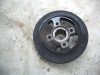
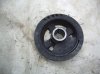
To start with this is a 94 K2500 with the 6.5 TD. I don't think the motor part of the job will be much, if any, different between the years, except between the mechanical injection and electronic injection pumps. I know the only real difference there is the mechanical IP motors need a harmonic balancer with a longer snout on them as the electronic IP requires a special spacer for the crank position sensor to read. However, I can't say the same for the vehicle frame between the years and GVW ratings. When I get into this you'll see why I bring up the frame.

PS: Hit the post button by accident so the next post will start the HB swap.

Don
 
Pic 1 & 2--- I always thought my harmonic balancer (HB) was in good condition (see first pic) as the rubber looked uniform all the way around, no splits or cracks in the rubber. But, I was unable to clearly see the back side, see second pic. Not so good, and since I have no history for this motor prior to about 160K I have no idea if it has ever been changed, 245K miles on the odometer.

Pic 3--- I removed the upper half of the radiator shroud, and fortunately I found a scrap of quarter inch plywood that was the perfect size to slip in as protection for the radiator. A piece of cardboard would also work. I also removed the belt and belt pulley that was on the HB.

Pic 4 & 5--- I struggled for a while trying to figure out how to hold the crank/HB steady for removal of the bolt holding the HB onto the end of the crank, until I hit on this idea. There is a hole in the frame directly below the HB. I used a 24" crow bar in the hole, and bolts in the pulley hole on the HB, to hold everything rock solid while removing the bolt. It's hard to explain, but a pic will show what I did. The bar is 3/4" thick and has a 1" wide tip. Anything with bigger dimensions wouldn't work.
 

Attachments

  • IMGP1672.jpg
    IMGP1672.jpg
    87.5 KB · Views: 23
  • IMGP1673.jpg
    IMGP1673.jpg
    86.8 KB · Views: 27
  • IMGP1660.jpg
    IMGP1660.jpg
    85.8 KB · Views: 24
  • IMGP1661.jpg
    IMGP1661.jpg
    57.3 KB · Views: 24
  • IMGP1662.jpg
    IMGP1662.jpg
    84.9 KB · Views: 25
Pic 1--- Here's how I set up the bar. However, this as shown is backwards for removal of the bolt as it won't keep the HB from turning in a counterclockwise direction. The bar needs to be on opposite sides of the pulley bolts to work for a counterclockwise turning of the HB bolt. I used a couple "sacrificial" bolts, 10mm X 1.50 X 65mm grade 8.8, as I didn't want to take a chance of damaging the stock pulley bolts. Grade 8.8 is a minimum as one of these bolts did get slightly bent in the process.

Pic 2--- To give you a better idea of how the hole in the frame, the crow bar, and the bolts all work together this pic is of the complete set up with the new HB going back in place. With the 3/4" thick bar there is just barely enough room to get the socket on the HB bolt.

Pics 3,4, & 5--- I replaced the front main seal while I had the HB out. Getting the old seal out was a pain. I messed around for a while trying to make a seal puller as I don't have one. There is only somewhere around 10" of space between the seal and the radiator, so the space to work in is small.What I made wasn't the greatest tool, but it was better than nothing. I didn't get any pics of my sorry excuse for a puller.

Here's what I did to make a seal driver for installation of the new seal. I went to Home Desperate and found this. It's a 2" X 3" ABS General Purpose Drain. It is designed to go over the outside of 3" ABS pipe. I then cut a short chunk of plastic electrical conduit (what I had available) and tapered about 3/4" on one end using my belt sander. I then slipped it loosely into the inside of the drain fitting. I didn't seat it all the way in, allowing it to slip deeper into the drain fitting if it bottomed out in the front cover before the new seal was all the way seated. The last pic is showing the new seal in place on the end of the driver. I very carefully cleaned the driver, the new seal and the seal pocket on the front cover, greased the new seals lip, and the tapered end of the tapered pipe.

I used a block of hardwood across the outer face of the driver to pound on while inserting the seal. Once the seal was started squarely in the opening the driver made short work of setting the seal.

PS: I hope the pics are end up in the correct order. They are listed in correct order in the manage attachments option, but in the preview are out of order.

PPS: NOPE!!! GRRRR!!!!! The third pic SHOULD be at the top of the pics. Don't have time to fight with it so just keep in mind that the third pic should have been the first pic to keep my narrative correct. My apology's.
 

Attachments

  • IMGP1663.jpg
    IMGP1663.jpg
    86 KB · Views: 18
  • IMGP1671.jpg
    IMGP1671.jpg
    81.5 KB · Views: 19
  • IMGP1666.jpg
    IMGP1666.jpg
    87.5 KB · Views: 18
  • IMGP1667.jpg
    IMGP1667.jpg
    79.4 KB · Views: 13
  • IMGP1668.jpg
    IMGP1668.jpg
    69.6 KB · Views: 13
Pic 1--- Somebody on this forum, I think it was WarWagon, told me about using the handle off his floor jack as a cheater for his breaker bar. GREAT IDEA!!! The HB bolt has a LOT of torque on it, over 200 ft lb if my memory is correct. The handle gave me a 48" cheater which made removing and replacing the HB bolt much easier.

Pic 2--- I was unable to find a bolt the right size with long enough threads in the threaded area. So I got two bolts, cut the heads off, did a deep V grind on the cut ends, and welded them together. The size was 16mm X 1.25 thread ( I think, better double check me on this).

I planned the length to be 4", but found out it could have been 3 1/4 to 3 1/2" long and work better. Sorry, no pics of this either. If anybody does the same as I did, make sure you get the V grind deep enough, and get a very good weld (let the weld cool slowly) as there is a very huge amount of tension on this "bolt" as you install the HB.

I threaded my special "bolt" all the way into the end of the crank. Then, after making sure everything was still very clean and the seal lip still had grease on it, I started the new HB onto the end of the crank. I used the heavy washer that was with the stock HB bolt, and a correct size metric nut on the exposed end of the "bolt".

By using this system the threads in the end of the crank are saved from any unneeded wear. The "bolt" and nut take all the abuse that happens when installing the new HB. To start with I was able to use my ratchet wrench to crank the HB into place. But, after a while I had to go to my breaker bar and cheater handle to keep from breaking my ratchet wrench.

Here's where my 4" "bolt" became too long. The last few turns of the nut got down to where I welded the two bolt ends together. I scrounged around and found a very large nut that would fit over the "bolt" end and act as a spacer between the heavy washer and the metric nut. This enabled me to get the new HB fully seated on the end of the crank.

I hope these pics and the description is of help to someone in the future.

Don
 

Attachments

  • IMGP1665.jpg
    IMGP1665.jpg
    87.3 KB · Views: 10
  • IMGP1670.jpg
    IMGP1670.jpg
    61.8 KB · Views: 12
Pic 3--- I removed the upper half of the radiator shroud, and fortunately I found a scrap of quarter inch plywood that was the perfect size to slip in as protection for the radiator. A piece of cardboard would also work. I also removed the belt and belt pulley that was on the HB.
I've tried cardboard and sheetmetal, but not plywood.
Cardboard sucks, as I whacked it hard enough and cut through to bleed out my knuckle.
With my luck, I'd get splinters from the plywood even if I varnished it.

Thanks for the diesel porn.
 
Nice write-up. I recommended the floor jack handle as a cheater bar. Instead of that crow bar to lock the crank, use a demo bar and run a bolt through he nail lifting hole on the flat end into one of the bolt holes on the HB. Brace the other rounded pry end against the cross member in the direction that you'll be torquing against.

A heavy pull with that jack handle will get you 200 ft lbs. I've tested it against rental torque wrenches.
 
I've been a bit busy since I posted this early Friday morning so I'm just getting back to this.

So it was Big T that had that great idea for using the floor jack handle as a cheater. My apologies for the mix up. It's a good thing my life doesn't depend on my memory. Anyhow, that is such a good one that it will forever be in my bag of tricks. Thanks Big T!!

At the moment I'm struggling with trying to picture how a single bolt through a demo/flat bar would hold the crank solid. I don't doubt you got it to work for you, I'm just not seeing it in my mind. However, the crow bar as pictured did lock the crank totally solid.

Daniel, let us know how things go for you when you do your HB.

Don
 
Don, you would still use 2 bolts, the second one would bind on the edge of the flat bar.
 
It works with one bolt. The standard demo bar will be bolted at the 9 or 3 o'clock position (removal or installation) with the claw jammed against the cross member, so all force will be straight down on the demo bar. It won't walk or slip to the side.

Your crow bar got it done with two bolts, so we both get there.

My favorite jack handle is off my American made Lincoln 2 ton floor jack. That handle is very thick pipe.

I've got the picture now. Yup, it would work real good.

With the end of the crow bar stuck down in the hole in the frame it won't move either. Both very viable solutions to a rock solid crank when removing the crank bolt.

Don
 
I've seen it recommended by one of the engine rebuilders associations to never reuse the HB bolt or washer.

I've also seen references to green loctite on the crank snout to fill in especially around the Key way. Then use red loctite on the bolt.

Anyone seen these recommendations?

Considering if the bolt comes loose, it will ruin a perfectly good engine! (see sig)
 
Anybody have any input on John's questions? I was considering using loctite on the HB bolt. but was also concerned about getting it loose again in the future. My motor has blowby and IF I can ever come up with the funds I want to get, at minimum, a Ted's military take out block to use.

Don
 
Always re-used the HB bolt and washer and never used loctite on it. The torque specs call for 180 ft lbs. That will never come loose.
 
Always re-used the HB bolt and washer and never used loctite on it. The torque specs call for 180 ft lbs. That will never come loose.

i thought is was 250ft/fb, My torque wrench, at the time was a max of 180 or 200. I went to the max and then some, and it still came loose. I did not use any thread locker either. (as in removed the bolt with my fingers after the crank snapped)

I had run across the comments when I was looking for a new motor and what had I F'd up when I changed the balancer. I tried finding them again, but my search failed.

A reminder of what happens if you mess this job up: :cussing:

attachment.php
 
I think I remember seeing the references over on the Page in the member section, under "6.2/6.5 AERA Technical Bul...". (AERA - Automotive Engine Rebuilders Association)

I can't verify since my membership lapsed.
 
Back
Top