• Welcome to The Truck Stop! We see you haven't REGISTERED yet.

    Your truck knowledge is missing!
    • Registration is FREE , all we need is your birthday and email. (We don't share ANY data with ANYONE)
    • We have tons of knowledge here for your diesel truck!
    • Post your own topics and reply to existing threads to help others out!
    • NO ADS! The site is fully functional and ad free!
    CLICK HERE TO REGISTER!

    Problems registering? Click here to contact us!

    Already registered, but need a PASSWORD RESET? CLICK HERE TO RESET YOUR PASSWORD!

Feed The Beast, Part I & Part II Improve fuel to IP

Status
Not open for further replies.
Had this in my FTB thread, so I'm bringing it over

3/8" fuel line = .11 sq in
4 x 3/16 holes = .11 sq in

1/4" fuel line = .05 sq in
4 x 1/8 holes = .05 sq in

So you see there is a reason for boring the holes. You only want to restrict the flow at the final inlet point if possible, and have strong enough supply pressure to keep the whole thing happy.
comparing the fuel line sizes to the 4 inlet holes is not to accurate IMO as the inlet orifice in the elbow as supplied by Leroy in his kit is only 1/4" wich in by my calculations is in area smaller than the combined area of the existing four 1/8" holes in the inlet tube,so the bottleneck is still right before the inlet,altough less so than with the stock barb.I aint disputing the FTB mode cause it will get the fuel there way less restricted than stock from the filter on.It does notting however for more flow trough the IP as the bores in the IP are just 3/16".

but maybe i'm just rambling.nuttin new,happened before:smile 5:
 
I think you meant Walking J.

All the fittings I use are 3/8" full flow, dont know about the 90 degree that comes with the FTB kit. Then I dont even use a angle, just straight in with 3/8" line.

I would expect a -6AN or 3/8" hose end fitting would match the 3/8" line its supposed to go with.

You cannot go wrong with larger supply, unless you dont have the pump to push the heavier mass. Like trying to use a fire hose to pump water out of a 80' silo. The guys couldnt understand why I told them to use an industrial garden hose instead.

If you calculate the area four 1/8" holes its EXACTLY the same as one 1/4" hole.
Yea,it was walking J.

A 3/8 barb has a smaller hole than the 3/8 hose.

I measured and calculated in metric,i come out with 3.39 sq mm more on the 4 holes than on my FTB hose barb.
1/2 dia x 1/2 dia x 3.14. gives area right!
 
yes you are right, pi x radius squared

I measured some 3/8" fittings I have and yeah, they are 9/32 in ID which would be .062 sq in area. So its still slightly larger than four 1/8" holes which is .05 sq in.

But go measure a 1/4' fitting and its way smaller.

Edit: I went and found all the 3/8" fitting I have and they do vary. The "full flow" ones I bought are the largest ID at 19/64" and another I had was just barely over 1/4" (like 1/128th over). I used all "full flow" fittings on mine. That area is about 0.07 sq in

Any way I look at it the less places of restriction the better. one fitting, 8 fittings, however many fittings there are reducing this spot where pressure is also regulated down and not just going though the four holes I think it makes a difference.
 
Last edited:
Th I.D.'s of the fittings varies most likely due to pressure limits of the fitting. All pipe under 12" is standard O.D. so the threaders will work.
 
The steel 3/8" to 7/16-20 upper IP fitting from Walking J is also 19/64 like all my "full flow" fittings from Russel Performance
Just to prove i aint BS'ing ye.Mebby a 1/4" is smaller in the US than in CAN,you guys pull that trick with the US gallon wich is smaller than a Imperial Gallon:D

Here's the pic,Walking J elbow,caliper tight in the hole.
Exactly 1/4" or 6.2 mm
 

Attachments

  • FTB fitting 003.jpg
    FTB fitting 003.jpg
    36.6 KB · Views: 70
Not doubting the elbow is that way. I was talking about the upper IP fitting. I didnt use any elbows, since I went straight up and on top of intake.

19/64" would be .07 sq in vs 4 x 1/8" holes which would be .05 sq in.

P1010414.jpgP1010415.jpg
 
I put the FTB mod in today,i did.nt drill the 4 holes in the IP inlet cause i did.nt see the point.

It sure makes a Diff in keeping the pressure up.
before at Wot 1 psi
After at Wot 3 psi
Gauge inlet post filter.
 
Nice addition to the thread fellas.... Now I see no point to drilling out my fitting unless I change out the bottle-necking elbow either. However, removing it and cleaning the screen is still a fantastic idea, so I might as well drill out my spare and swap that in there when the time is ready.
 
Then you'll never know the difference or be able to deny a difference :frown2:

You can at least admit there is a difference between a 90 degree radius bend and pushing the same volume of fluid through 4 smaller holes of equal area at a 90 degree angle, at a point of regulation in the perpendicular direction too.

Not all of us take our trucks to the limit though, so for many people it wont really matter. Should we start the 130+mph club ;)
Yea Buddy ,in theory you're right,but after the fuel passes trough the inlet and screen,the next step is trough a 3/16" orifice in a banjo bolt before entering the transfer pump.Now we're back to square one.:kiss:

If i want to race,i'll buy a formula one:smile5:
 
Important(!!!) New (?) Discovery(?) on Feed The Beast Mods

Howdy, All...

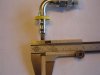
Stuttering on acceleration for a long time, slowly getting worse...finally put in a fuel pressure gauge.

Meantime, I had dropped and cleaned the fuel tank, replaced the lift pump, cleaned out the fuel manager.
I actually replaced the lift pump with a Shurflo 5000-series 1.5GPM triple diaphragm pump,
regulated to 10 psi with a polypropylene external pressure relief valve.
Still had 10 PSI at idle, dropped to 0 on light acceleration, heavy vacuum on heavy acceleration.

Finally decided to do the FTB mods. I did them slightly differently; I'll describe what I did in a separate post.

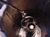
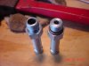
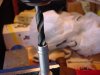
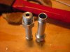
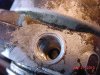
I discovered something IMPORTANT while doing the FTB mods. I drilled out the filter/manager housing, installed the new barb, flushed, etc. and tried blowing through it...I STILL had a LOT of back pressure!!!

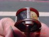
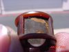
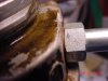
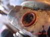
The little cylindrical fuel strainer in the middle of the fuel filter housing was BADLY clogged. I have seen it mentioned in other threads, as in "make sure it's still there; it can sometimes be removed accidentally when you remove the fuel filter element." But I read everything I could find on the FTB mods, including on the old site, and nobody seems to have made the point that this little screen needs to be pulled and cleaned.

Now granted, I have 433k miles on my truck, and mine was probably clogged a little more than average, but...it didn't happen overnight. I can't help but wonder what would have happened to my fuel pressure if I had cleaned it BEFORE I did the FTB mods...and I can't help but wonder how many other guys' fuel pressure problems might be caused by this little screen being clogged?

Getting it out was a bit difficult. I pulled and pulled, and it moved a little, but it seemed to be stuck. Then I noticed that it as it moved, it was scraping up more black stuff from the hub...I scraped the hub clean, and the filter came off pretty easily.

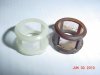
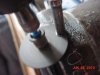
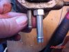
I scraped it clean...the black stuff clogging it was hard, like dried gummy sludge. Gotta be careful you don't poke through the screen...I backed the screen with my finger, and was very careful. Used lots of spray Gumout. After I cleaned it, I decided to replace it anyway...it is definitely NOT a dealer item, it is a Stanadyne part, part no. 29244. $2.43 plus shipping.
http://www.btlrus.com/99717B.pdf (page 11)

Incidentally, my fuel pressure is now a steady 10 at idle, and drops to about a steady 7 under all but the heaviest acceleration. I am measuring pressure right at the IP inlet.

On heavy acceleration, it drops towards zero, but...lots of black smoke. The Heath boost regulator is my next mod.

Forewarned is forearmed...!!

--Clipper
 

Attachments

  • DSC00665.JPG
    DSC00665.JPG
    31 KB · Views: 61
  • DSC00603.JPG
    DSC00603.JPG
    47.6 KB · Views: 60
  • DSC00601.JPG
    DSC00601.JPG
    38.6 KB · Views: 66
  • DSC00596.JPG
    DSC00596.JPG
    44.9 KB · Views: 76
One piece barbs for Feed the Beast Mods

Howdy, All...

First, I cut the old barb off with a Dremel tool. Seemed to me easier than a hacksaw.

I found a #4ORB to 3/8 barb in one piece; it's made by Brennan and available through industrial hose and pipe suppliers. I bought two; 2.63 each plus shipping. Here is the Brennan spec page:
http://www.brennaninc.com/ProductDisplay.asp?pg=productdisplay&item=4604-06-04-O
Thanks to all of you who blazed the trail; without you I wouldn't have known I needed a #4ORB!!

Drilled the filter housing out; the #4 thread (7/16-20) takes a 25/64 drill. NOTE: you DON'T need to drill the big hole all the way through to the fuel port in the center; you just need to drill it deep enough to tap the length of the threads on the fitting. Then you can drill the .250 fuel hole (discussed elsewhere) all the way to the fuel port in the center of the housing. As mentioned in other postings, measure the depth, then mark your drill with a ziptie...you DON'T want to drill into the center hub of the fuel housing. I used grease in the drill flutes to keep as many metal chips as possible from falling in the hole. I tapped the hole with a bottom tap, so it wouldn't project too far into the hole. The metal was so soft, it was easy to start the tap.

With a 1/2" drill, I created a countersink in the filter housing, to hold the O-ring. The metal of the filter housing is very soft; you don't need to press very hard or spin the drill very fast. You don't want to countersink too "deep;" you want the O-ring to have some "squish." If you try to squish it between two flat surfaces, it can be forced outwards and you will have no seal. You need that bevel to keep the seal in place. Viton O-rings, of course.

I also drilled out the new fittings a little, because the hole on the #4 end is smaller than .250. The hole in the barb is about 1/32" larger than .250, so that is the drill I used; the barb hole acted as a guide for the drill.

The rest is pretty straightforward; the new #4 fittings fit perfectly into the IP fitting.

--Clipper
 

Attachments

  • DSC00593.JPG
    DSC00593.JPG
    47 KB · Views: 78
  • DSC00589.JPG
    DSC00589.JPG
    39.8 KB · Views: 84
  • DSC00587.JPG
    DSC00587.JPG
    38.1 KB · Views: 85
  • DSC00585.JPG
    DSC00585.JPG
    34 KB · Views: 87
  • DSC00584.JPG
    DSC00584.JPG
    50.3 KB · Views: 83
  • DSC00583.JPG
    DSC00583.JPG
    54.3 KB · Views: 86
  • DSC00581.JPG
    DSC00581.JPG
    46.5 KB · Views: 88
  • DSC00594.JPG
    DSC00594.JPG
    48.5 KB · Views: 87
Status
Not open for further replies.
Back
Top