Acesneights1
New Member
TD edit, gonna be a little out of order per Aces request I merged them, his version Pt II, though posted before mine Pt I done at old site, & reposted here later; so pt II will appear before pt I
OK So it's time to rebuild the knowledge base. I'll try to do my part here since I just did this Mod it's still fresh in my mind. This mod was originally designed/created by Turbine Doc. I used a couple different fittings so Here goes. I never did a whole write up before so Mods feel free to edit as nessicary.
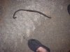
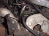
OK So in our quest for more performance with Improved Eproms, Mechical waste gate controllers etc we also need better fuel delivery to the Injection Pump. Has anyone ever really looked at the Fuel line feeding the IP from the Fuel Manager(aka Fuel Filter) ? It's tiny. Looks like Vacuum line. Don't remember the actual measured size from the orignal write up but suffice to say it's small and when we increase the power of the engine and the IP tries to draw fuel faster than the Lift pump can deliver through this bottle neck we can actually end up with a vacuum. Never set up a gauge myself but others have reported that.
So now with a little history behind the idea we move on to the task. The nice thing about this mod is it's very low cost. There has also been specualtion that the lack of free flowing fuel through the bottle neck may have also contributed to the failure of GM's big Idea of cooling the PMD with fuel flow.
We'll start with the fuel manager first. IP fitting mod later.
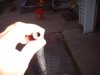
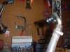
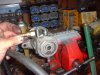
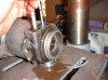
So we start by disconnecting the fuel manager. There are two 15 MM Bolts that hold it to the rear of the intake manifold. It has three lines on it and the wires for both the fuel heater and water in fuel sensor. There is an influent line which is about 3/8 inch. Nice and healthy flow coming in. Then on the other effluent side(can you tell I work for the Water Dept ?)or out to IP we have this little guy that looks like windshield washer hose(well maybe slightly bigger). Then we have the hose that goes to the drain in the front of the motor.
OK so now we have disonnected all the lines and removed the fuel manager(it's proper name). Now dissasemble it. Take the top ring off that holds in the filter(If you can't figure that one out maybe you should stop at this point:crazy") . Then take the bottom ring off which holds in the fuel heater rod. Now remove the water in fuel sensor off the side(2 screws forgot the size but need a nutdriver). Also don;t forget to remove the last ditch screen. If it's missing you need to get another one. I don't have a pic but maybe someone else does. You cannot get it from the dealer. ONly a stanydyne dealer. Part# to come. These often get stuck in the fuel filter and discarded so your might be missing. Mine were in both my rides.
. Then take the bottom ring off which holds in the fuel heater rod. Now remove the water in fuel sensor off the side(2 screws forgot the size but need a nutdriver). Also don;t forget to remove the last ditch screen. If it's missing you need to get another one. I don't have a pic but maybe someone else does. You cannot get it from the dealer. ONly a stanydyne dealer. Part# to come. These often get stuck in the fuel filter and discarded so your might be missing. Mine were in both my rides.
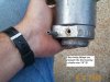
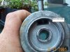
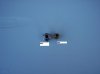
Now we have our stripped down housing ready for mod.
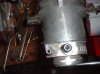
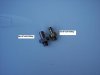
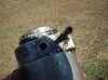
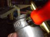
We take our effluent or out side of the filter and cut the fitting off nice square and flush with teh housing. This fitting is pressed in but we are going to drill it out after cutting it flush.
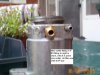
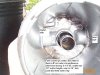
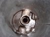
OK now that we have cut our out fitting flush there is no turning back so here comes the tricky part. drilling out the old fitting large enough for 1/8 NPT. Now BEFORE Drilling look into the fuel manager from the top. See the nice shiny sleeve that the filter slides down on ? You have very little clearence between that and where you will be drilling into so BE CAREFUL. If you drill to far and into that middle part, you got a 300$ paperweight. If you are not comfortable with precise drilling, bring it to a machine shop but me myself am not all that great and I did it so it can be done by the average guy.
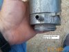
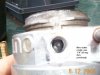
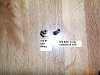
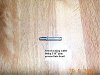
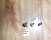
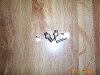
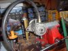
I drilled with a nice brand new sharp 5/16 bit all the way through the housing but not hitting the middle part. I measured the depth I would need to go to penetrate the housing without hitting the inside part and then put a zip tie on the drill bit at a slight less as a makeshift depth gauge. Once I drilled in out successfully I used a really skinny pick to get in there to deburr the insde between the housing and sleeve. Now use a 1/8 npt pipe tap. Don't go too deep because the tap is tapered you you want the new fitting you are going to install to thread just about all the way in but not quite so it kind wedged itself in for a nice seal. I did trial and error. I tapped a little then tried the fitting. Took about 3 tries to get it where I wanted. Now IIRC this is where I veered off what Turbine Doc did. TD correct this as nessicary as I don't have the old sticky to reference. You can use a 3/8 barbx1/8npt and then hose clamp and fuelline from here but i wanted to go the extra mile to make it look neat. There is nothing wrong with teh 3/8 barb and hose clamp. I used a #6 37deg malex1/8 NPT hydrualic fitting. Now inside this fitting the opeing gets smaller. I drilled it out the same size all the way through which I believe was like.280 All I know is it ended up being the same size ID as if I had used the 3/8 barb( I had one but didn't use it) Now I took a viton 3/8 fuel inj line and put a 3/8barbx#6 female. The reason I did this extra work was so the fuel line would be easy to remove instead of wrestling with getting it off the barb if I ever needed to remove the fuel manager later on for any reason. Ever try to get fuel Inj line off a barb ? Not easy and at like 6$ a foot I didn't want to have to cut it off. Here's the pics. It's late. I'll do the IP end of this tommorow night.
OK So it's time to rebuild the knowledge base. I'll try to do my part here since I just did this Mod it's still fresh in my mind. This mod was originally designed/created by Turbine Doc. I used a couple different fittings so Here goes. I never did a whole write up before so Mods feel free to edit as nessicary.
OK So in our quest for more performance with Improved Eproms, Mechical waste gate controllers etc we also need better fuel delivery to the Injection Pump. Has anyone ever really looked at the Fuel line feeding the IP from the Fuel Manager(aka Fuel Filter) ? It's tiny. Looks like Vacuum line. Don't remember the actual measured size from the orignal write up but suffice to say it's small and when we increase the power of the engine and the IP tries to draw fuel faster than the Lift pump can deliver through this bottle neck we can actually end up with a vacuum. Never set up a gauge myself but others have reported that.
So now with a little history behind the idea we move on to the task. The nice thing about this mod is it's very low cost. There has also been specualtion that the lack of free flowing fuel through the bottle neck may have also contributed to the failure of GM's big Idea of cooling the PMD with fuel flow.
We'll start with the fuel manager first. IP fitting mod later.
So we start by disconnecting the fuel manager. There are two 15 MM Bolts that hold it to the rear of the intake manifold. It has three lines on it and the wires for both the fuel heater and water in fuel sensor. There is an influent line which is about 3/8 inch. Nice and healthy flow coming in. Then on the other effluent side(can you tell I work for the Water Dept ?)or out to IP we have this little guy that looks like windshield washer hose(well maybe slightly bigger). Then we have the hose that goes to the drain in the front of the motor.
OK so now we have disonnected all the lines and removed the fuel manager(it's proper name). Now dissasemble it. Take the top ring off that holds in the filter(If you can't figure that one out maybe you should stop at this point:crazy
. Then take the bottom ring off which holds in the fuel heater rod. Now remove the water in fuel sensor off the side(2 screws forgot the size but need a nutdriver). Also don;t forget to remove the last ditch screen. If it's missing you need to get another one. I don't have a pic but maybe someone else does. You cannot get it from the dealer. ONly a stanydyne dealer. Part# to come. These often get stuck in the fuel filter and discarded so your might be missing. Mine were in both my rides.Now we have our stripped down housing ready for mod.
We take our effluent or out side of the filter and cut the fitting off nice square and flush with teh housing. This fitting is pressed in but we are going to drill it out after cutting it flush.
OK now that we have cut our out fitting flush there is no turning back so here comes the tricky part. drilling out the old fitting large enough for 1/8 NPT. Now BEFORE Drilling look into the fuel manager from the top. See the nice shiny sleeve that the filter slides down on ? You have very little clearence between that and where you will be drilling into so BE CAREFUL. If you drill to far and into that middle part, you got a 300$ paperweight. If you are not comfortable with precise drilling, bring it to a machine shop but me myself am not all that great and I did it so it can be done by the average guy.
I drilled with a nice brand new sharp 5/16 bit all the way through the housing but not hitting the middle part. I measured the depth I would need to go to penetrate the housing without hitting the inside part and then put a zip tie on the drill bit at a slight less as a makeshift depth gauge. Once I drilled in out successfully I used a really skinny pick to get in there to deburr the insde between the housing and sleeve. Now use a 1/8 npt pipe tap. Don't go too deep because the tap is tapered you you want the new fitting you are going to install to thread just about all the way in but not quite so it kind wedged itself in for a nice seal. I did trial and error. I tapped a little then tried the fitting. Took about 3 tries to get it where I wanted. Now IIRC this is where I veered off what Turbine Doc did. TD correct this as nessicary as I don't have the old sticky to reference. You can use a 3/8 barbx1/8npt and then hose clamp and fuelline from here but i wanted to go the extra mile to make it look neat. There is nothing wrong with teh 3/8 barb and hose clamp. I used a #6 37deg malex1/8 NPT hydrualic fitting. Now inside this fitting the opeing gets smaller. I drilled it out the same size all the way through which I believe was like.280 All I know is it ended up being the same size ID as if I had used the 3/8 barb( I had one but didn't use it) Now I took a viton 3/8 fuel inj line and put a 3/8barbx#6 female. The reason I did this extra work was so the fuel line would be easy to remove instead of wrestling with getting it off the barb if I ever needed to remove the fuel manager later on for any reason. Ever try to get fuel Inj line off a barb ? Not easy and at like 6$ a foot I didn't want to have to cut it off. Here's the pics. It's late. I'll do the IP end of this tommorow night.
Attachments
Last edited by a moderator: