Missy Good Wench
Wild Blonde from Cloud Mt
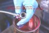
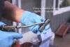
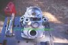
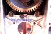
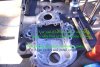
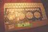
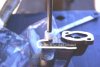
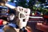
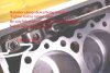
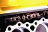
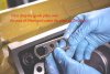
More tips and pix on assembly of the 6.5/6.2 engine
Attachments
-
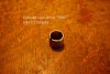
 Cover gasket.JPG39.1 KB · Views: 142
 -
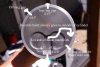
 front case inner bolts.JPG32.4 KB · Views: 139
 -
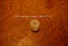
 Front cover seal.JPG33.1 KB · Views: 136
 -
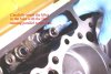
 Head dowels.JPG23.5 KB · Views: 125
 -
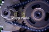
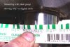
 Mark oil pump.JPG31.3 KB · Views: 149
 -
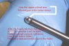
 Oil pump with shaft.JPG20.2 KB · Views: 134
 -
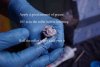
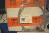
 oilpuump shaft coupler.JPG25 KB · Views: 123
 -
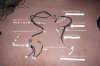
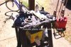 workbench.JPG50.6 KB · Views: 142