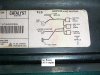
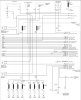
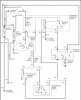
PMD pin out:
A - FI Control from PCM - Grn
B - FSol+ drive from FSD - Red large
C - Closure grnd to PCM - Blk small
D - +12v switched power - Pnk - same as ESO solenoid power
E - FI Signal to PCM - Red small
F - FSol- drive grnd for FSD - Blk large, also attached to the top of the Inj Pump ONLY - NO MOVE - NO EXTENSION -TOP OF THE INJECTION PUMP, ONLY - PERIOD!!!!!!!!!!!
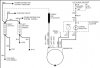
Idiots guide to PMD wires
A- Green wire from puter. Tells it what to do.
(Fire the injectors)
B- Red wire goes to back of pump to the poppet valve solenoid
(Triggers the firing)
C- Black wire goes to puter so puter has a ground like PMD
(Good grounds make happy puters)
D- Pink wire goes to ignition and the electric shut-off solenoid
(That silver shiny cylinder thing up front thing) 12volts or better on a good day.
E- Another red wire, goes to puter and tells it what the pulse width is to the puter.
(So it can throw up a code when the pump or PMD is shot. 35 or 36 take your pick)
F- Another black wire, goes to back of pump to the poppet valve solenoid
(grounds the solenoid so it will fire when the PMD sends it some juice)
Resister goes between E and D just so the fuel output can be tweaked just a little.
Thanks to gmctd and diesel pro for the info
A - FI Control from PCM - Grn
B - FSol+ drive from FSD - Red large
C - Closure grnd to PCM - Blk small
D - +12v switched power - Pnk - same as ESO solenoid power
E - FI Signal to PCM - Red small
F - FSol- drive grnd for FSD - Blk large, also attached to the top of the Inj Pump ONLY - NO MOVE - NO EXTENSION -TOP OF THE INJECTION PUMP, ONLY - PERIOD!!!!!!!!!!!
Idiots guide to PMD wires
A- Green wire from puter. Tells it what to do.
(Fire the injectors)
B- Red wire goes to back of pump to the poppet valve solenoid
(Triggers the firing)
C- Black wire goes to puter so puter has a ground like PMD
(Good grounds make happy puters)
D- Pink wire goes to ignition and the electric shut-off solenoid
(That silver shiny cylinder thing up front thing) 12volts or better on a good day.
E- Another red wire, goes to puter and tells it what the pulse width is to the puter.
(So it can throw up a code when the pump or PMD is shot. 35 or 36 take your pick)
F- Another black wire, goes to back of pump to the poppet valve solenoid
(grounds the solenoid so it will fire when the PMD sends it some juice)
Resister goes between E and D just so the fuel output can be tweaked just a little.
Thanks to gmctd and diesel pro for the info