• Welcome to The Truck Stop! We see you haven't REGISTERED yet.

    Your truck knowledge is missing!
    • Registration is FREE , all we need is your birthday and email. (We don't share ANY data with ANYONE)
    • We have tons of knowledge here for your diesel truck!
    • Post your own topics and reply to existing threads to help others out!
    • NO ADS! The site is fully functional and ad free!
    CLICK HERE TO REGISTER!

    Problems registering? Click here to contact us!

    Already registered, but need a PASSWORD RESET? CLICK HERE TO RESET YOUR PASSWORD!

Hummer Fan clutch setup

Chief915

915A Maint Tech
Messages
406
Reaction score
1
Location
Cecilia, KY
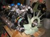
BTW, Chief915...you had mentioned being a Mil Mechanic and working on Humvees...I would love to see some detailed pics of the clutch setup they use. I was told it's hydraulic but I have never seen it. Can they be engaged manually ? Serp belt or V ?? CW or CCW ?

To answer your questions;

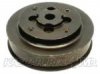
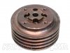
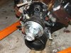
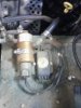
The fan clutch is hydraulically controlled for "locked" or "unlocked". It uses power steering fluid pressure routed through an elctro-hydraulic solenoid that locks up the fan clutch just like a clutch pack would be in an automatic trans. The solenoid operated (to lock the fan clutch) by the small black box next to it in the pic. The fan clutch on these is either completely on (spinning at water pump speed) or completely off (free wheeling).... no in between.

Normally, the fan cannot be engaged manually by the driver. In other words, there is no "switch" inside the hummer to turn the fan on whenever they want. It is managed and turned on or off automatically based on engine temps. However, in a pinch, unplugging the black box next to the fan solenoid will make the fan on continuously.

V-belts and serp belts are both used on hummers, it all depends on the model. V-belt's use CW water pumps while serp belt systems use CCW HO pumps just like the civilian trucks.

This is some info out of the Hummer operator's manual, which is kinda like an owners manual.

This is for "light duty" (more or less, to break it down in easy to understand terms) Hummers

Table 1-6. Cooling System Data
Surge tank cap pressure . . . . . . . . . . . . . . . . . . . . . . . . . . 15 psi (103 kPa)
Thermostat:
Starts to open . . . . . . . . . . . . . . . . . . . . . . . . . . . . . . . . . . 190°F (88°C)
Fully open . . . . . . . . . . . . . . . . . . . . . . . . . . . . . . . . . . . . 212°F (1 00°C)
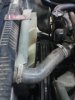
Radiator . . . . . . . . . . . . . . . . . . . . . . . . . . . . . . . . . . . . . . Downflow type
Fan . . . . . . . . . . . . . . . . . . . . . . . . . . . . . . . . . . 10 blade, 19 inch (48 cm)
Normal operating coolant temperature . . . . . . . . . . 190°-230°F (88°-110°C)


And this table is for "heavy duty" hummers.

Table 1-5. Cooling System Data.
Surge tank cap pressure . . . . . . . . . . . . . . . . . . . . . . . . . . . . . . 15 psi (103 kPa)
Thermostat:
Starts to open . . . . . . . . . . . . . . . . . . . . . . . . . . . . . . . . . . . . . . 190°F (88°C)
Fully open . . . . . . . . . . . . . . . . . . . . . . . . . . . . . . . . . . . . . . . . 212°F (100°C)
Radiator . . . . . . . . . . . . . . . . . . . . . . . . . . . . . . . . . . . . . . . . . . Downflow type
Fan (serial numbers 299999 and below) . . . . . . . . . . . . . 10 blade, 19 in. (48 cm)
Fan (serial numbers 300000 and above) . . . . . . . . . . . . . .9 blade, 23 in. (58 cm)
Normal operating coolant temperature . . . . . . . . . . . . . . 185°–250°F (85°-120°C)


Notice the "normal operating coolant temprature" ratings on each one........... :eek:


Here's more stuff out of the operator's manual:

ENGINE TEMPERATURE SWITCH – Sends signal to activate control
valve system to operate fan when engine temperature exceeds 220°F (104°C)
and deactivates control valve system when engine temperature drops below
190°F (88°C).

HYDRAULIC CONTROL VALVE – Directs hydraulic fluid to provide
required pressure to actuate fan clutch as required by engine temperature.
Hydraulic pressure supplied by power steering pump.

FAN CLUTCH – Hydraulically actuated by pressure from hydraulic control
valve to control operation of fan. Hydraulic pressure supplied by power
steering pump.
 

Attachments

  • hmmwv clutch 3.jpg
    hmmwv clutch 3.jpg
    84.9 KB · Views: 60
  • fan setup.jpg
    fan setup.jpg
    29.5 KB · Views: 61
  • 2.jpg
    2.jpg
    28.6 KB · Views: 64
  • hmmwv 4.jpg
    hmmwv 4.jpg
    49.9 KB · Views: 70
Last edited:
Very interesting. Thanks for posting. Crazy high temps allowed. No wonder there is so many take outs.
Now the real question. How do we civilians get our hands on a set up like that? I have 7 of the v-belt clutches but would never switch anything to a v-belt.
 
X2, do you have any pics of the serp style ? Also I notice you posted Hummer...So this info is the civvy version or Mil ? I really really like this. I was unaware they came in serp...I would think this setup could easily be retrofitted to our trucks and the late engagement could also easily fixed as well as an override switch wired in. Please...go on...me likey alot. Does the serp style use the same 99+ thread on WP the civvy PU's use ?
 
Thats the "new replacment" fan for 96 and earlier......The white 10 blade 19" Plastic/composite.

Friend of mine replaced the one on his 96 suburban and thats what they gave him from the dealer.....No more 6 blade metal/steel....Is the 19" a 6 bolt deal?

Chief, you got a pic of the 23" 9 blade?.......What color is it?

No getting around trimming the shroud for that 23" bad boy!
 
Also I notice you posted Hummer...So this info is the civvy version or Mil ?

This info is all Military..... The Army acronym for a hummer is: HMMWV ..... which means High Mobility Multipurpose Wheeled Vehicle, but figured hummer was more easily understandable.

How do we civilians get our hands on a set up like that? I have 7 of the v-belt clutches but would never switch anything to a v-belt.

It's actually the same exact fan clutch for both v-belt and serp setups.

The pulley (either v-belt wp pulley or serp belt wp pulley) bolts to the water pump pump with 4 allen head bolts. (These are the same "flange style" water pumps we use on our chevy 6.5 trucks.) Then the fan clutch bolts to the pulley using 4 different/seperate allen head bolts.

So long story short..... the 7 HMMWV fan clutches you have will work on either a serp belt HMMWV setup or a V-belt HMMWV setup.

Does the serp style use the same 99+ thread on WP the civvy PU's use ?

No, we use flange style pumps, which are the same flange style pumps the civvy PU's use. HMMWV's don't use any thread on style pumps.


Part #s ???
:D

Some of these "look" like GM or Delco part numbers and some don't. I can research them more to find out when I get back to work tomrrow.

Fan blade (19.5" 10 blade) 4735-42599-103 or 12460252 (23" 9 blade) 4735-43782-18

Fan Clutch 1090-06404-01

Serp Belt Pulley 12469472

Fan clutch control (electro-hydraulic solenoid) 12339982 NOTE: This is going to be a 24V solenoid..... not sure how to work around that.

Serp belt pulley to water pump bolts: (part number 12339240) size M8-1.25 X 20MM Must be allen head bolts and 4 are required.

Fan clutch to serp belt pulley bolts: (part number 138242) 3/8-16 X 1.00 Must be allen head bolts and 4 are required.

Fan blade gets held on to the fan clutch by 4 3/8-16 nuts and lock washers.


Thats the "new replacment" fan for 96 and earlier......The white 10 blade 19" Plastic/composite.

Is the 19" a 6 bolt deal?


Not on the HMMWV's. It's held to the fan clutch with 4 studs and nuts. It must be a different than "new replacement" fan that you are referring to.

Chief, you got a pic of the 23" 9 blade?.......What color is it?

Not yet, those are in "brand new" HMMWV's, which I don't have any of. I will dig around and see what I can find.
 
Last edited:
I would think the part numbers are am general/gep numbers.
I'll have to take one of mine apart to see how the thing works and pulley replacement. I should just need the control valve and temp sensor.
 
This is great stuff. So Heath's cooling upgrade does not contain a mIl umvee WP, it can't if it's thread on. OK I think I got this. It seems the hardest thing to obtain is the serp pulley. Then one would need a 98 WP. The only other question would be if the serp pulley lines up with our existing accessories. I got to look at that TM. I'm really liking this. I'd blow 300$ on a clutch without thinking about it if it could be rigged to be controlled manually as well as automatic. I had heard of this setup but until you did this thread thought they could only be used with V belts. Why hasn't someone tried this yet ?

Being that you work n these alot, how is the reliability ?
Hmmm...my burb has a 98 WP...I smell an experiment....
 
Reliability is alright.... Biggest problem to be honest is the electrical controller (little black box). It goes out, then the fan doesn't come on. If you were to rig one of these up with a toggle switch, to turn it on whenver you like, it would be great.

I can tell you these fans and a fully locked fan clutch move A LOT of air. Riding along at about 2,000 - 2,200 rpm and the fan kicks on..... Sounds like a prop airplane at full throttle.
 
I'm thinking for this experiment, I would probably try and get the serp pulley first and see if it lines up. Then blow the big wad...
 
Don't see why not. The clutch is sealed internally to keep fluid from spewing out of it.... Anything that will hold fluid pressure should hold air pressure too. Air activated may be much easier to do than going the P/S fluid route.
 
Don't see why not. The clutch is sealed internally to keep fluid from spewing out of it.... Anything that will hold fluid pressure should hold air pressure too. Air activated may be much easier to do than going the P/S fluid route.

That is what I am thinking. The only issue would be how much pressure the clutch needs for lock up. Not sure what PSI the power steering runs.
 
wait a minute...duh..if the Hyd clutch uses the same WP as a 98 Civvy why couldn't I use the pulley from the civvy ?


The fan clutch bolts to the pulley itself, not to the water pump like on the 98's.

The pulley is a beefy cast pulley, not the stamped steel version on the 98's. The serp pulley bolts to the water pump using 4 bolts...... Then the fan clutch bolts to the pulley with 4 other bolts. It's a different set up than your 98 where the pulley and fan clutch are all held on by the same 4 studs.

The bolt circle on the clutch is bigger than the bolt circle on the water pump.


The 4 holes closest to the middle of the pulley are for the bolts that hold the pulley to the water pump. The outer 4 holes are for the fan clutch to bolt to the pulley.
 

Attachments

  • pulley 1.jpg
    pulley 1.jpg
    3.8 KB · Views: 120
  • pulley 2.jpg
    pulley 2.jpg
    41 KB · Views: 11
Back
Top