
- Staff
- #1
This is some basic info I have put together from the ALLISON 4th generation troubleshooting and service manuals as well as ALOT of internal studying of parts and studying of the TRANSGO patent application they filed.
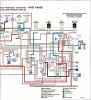
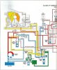
Here is the fluid flow diagrams.
park/neutral

normal reverse

reverse in limp mode(hydraulic only)

3rd in limp(default when the TCM limps)

1st gear

2nd gear

3rd gear

4th gear

5th gear

6th gear

LEGEND:
PCS1=Trim A
PCS2=Trim B
SS1=C shift solonoid
SS2=D shift solonoid
SS3=E shift solonoid
MAIN MOD= G solonoid
TCC=F solonoid
SV1=C shift valve
SV2=D shift valve
SV3=E shift valve
And these are the shift tables that describe what happens with which solonoid for which shift.


As you can see from the diagrams, the ALLISON shifts in a fairly unusual manner. All oncoming or offgoing clutch packs are controlled via the 2 trim solonoids and trim valves for how fast and how much pressure they receive. Once a shift occurs, then the shift valve will change position to allow the trim solonoids to work for the next shift. So only one trim solonoid can send out fluid at one time or else you get a tie up(2 gears at once). Trim A(PCS1) and Trim B(PCS 2) wil always alternate each other so as to control the offgoing with one and the oncoming with the other. Trim A is default on while Trim B is default off, this is how they accomplish limp mode hydraulically as the trim A will feed the C3 clutch when no solonoids are powered, and the manual shift valve will transfer main line pressure to either the C5 or C1 in limp mode. this a rather complex shift strategy where 3 motions are done on each shift, a trim goes off while one comes on and then a shift valve moves.
The 3-4 shift is an unusual one though as it pulses on the B to engage the C2 clutch then it transfers the main line pressure from the C1 clutch over to the C2 clutch via the E-shift valves movement. And at teh same time it transfers the C2 to main from teh C1, it is also transferring the C1 to trim B. In stock trim this is where the weakness comes in as the C1 clutches will receive full line pressure(roughly 240-250 PSI) for 1st-3rd, but drop to roughly 140 during the transfer from the E shift valves changeover. This is the only shift where I can see that the shift valves really change fluid to the clutches and why it is so troublesome. And the C3, C4, and C5's only work on trim valve pressures so in stock form they never see more than the 140 that the Trim's can provide.
The ALLISON also utilizes an exhaust backfill circuit to prefill the psito nassemblies with fluid to allow for more accurate and consistent control of teh clutches by having more conssitent variables. It runs at roughly 2-4 PSI, and is supllied via the control main valve in the valve body and regulated for pressure by the exhaust backfill valve. It primarily fills the C-3, C-4, and C-5 clutches. It also feeds the C1 clutch in a limited quantity due to the C1 clutch control valve that exhausts the C1 when not applied, and the C2. The C1 clucth reives backfill also by fluid transfer at the stator where the C1/C2 roating assembly gets its oil feed through the ports sealed by sealing rings.
The trim solonoids that come in the TRANSGO kit are recalibrated to allow full line pressure to be sent out as they are supplied via full main line pressure to begin with(the stock valves were calibrated to limit them to only 140 max though out). They have the check ball in the end of them in order to allow full main line pressure to be applied to the trim circuits once the pressure is high enough to overcome the spring that holds the check ball closed. When the trim valve is trimmed off the check ball will close and only allow what the factory calibration would allow. This is how they accomplish teh faster shifts without relearn. This is also why people get violent downshifts if they leave teh checkballs out of teh trim valves as this will alow full line pressure to act upon the closing of the valve and full line pressure to figure into the release instead of modulated pressure.
The C2 mods that come in teh kit are simliar but not exact to there origanal patent submissions. The C2 piston works as a 2 way piston in one. It has the larger of it's apply areas on theside that applies it to the C2 clutches, but it also utilizes a balance piston that works to oppose it which causes a cushion and reduces total clamping force. The first TRANSGO idea was to utilize the area between the 2 pistons and use it as a dampner for apply but increase surface area once applied. This would beaccomplished by reducing the bleed hole in the C2 rotating drum down to a very small .017 orifice and then drill a small hole through the side of the C2 psiton into the balance pistons apply fluid passage effectively increasing the apply but doing it in such a way as to limit how fast it could be applied via the use of orifice plugs. The second design was to plug off the 2 balance piston feed ports and remove the balance piston all together and change out the release springs with stiffer ones to dampen the application of the C2. The method they decided to go with was one of simplicity and functionality. They decided to use .012 orifice plugs inside of the .110 balance piston feed ports and drill a hole in the C2 piston which would bleed off all of the balance pistons fluid so it would not be able to act against the C2 piston any longer. They left the balance piston in for centering purposes and installed stiffer return springs to help offset the increased applied force and lack of a dampening piston. This method is very simliar to there second C2 patent suggestion, but it does not completely block off teh C2 feed ports like they described in there patent(the orifice plugs they chose to use are a commonly available plug available for the 4L60 trans for the reverse input drum mods).
From my bench tests via air pressure, there method actaully actuates slower than a stock C2 arrangement. I'm still working on a different style set-up to see if I can smooth it out some more, even though my method goes against all conventional thinking(but I believe it goes more in line with ALLISONS thinking behind the 6 speed changes).
I don't claim to be an expert and I didn't even stay at a Holiday Inn last night, but I have found that I am pretty good at deciphering and reverse engineering via technical manuals and illustrations. If I made any mistakes PLEASE feel free to correct me as it will help all of us. And for some reason the uploader shrunk my pics down.
TRANSGO patent info and descriptions found here. http://www.patentgenius.com/patent/7128679.html
ALLISON info was obtained via the Gen 4 troubleshooting manual(TS3977EN) and the service manual(SM4006EN).
Here is the fluid flow diagrams.
park/neutral
normal reverse
reverse in limp mode(hydraulic only)
3rd in limp(default when the TCM limps)
1st gear
2nd gear
3rd gear
4th gear
5th gear
6th gear
LEGEND:
PCS1=Trim A
PCS2=Trim B
SS1=C shift solonoid
SS2=D shift solonoid
SS3=E shift solonoid
MAIN MOD= G solonoid
TCC=F solonoid
SV1=C shift valve
SV2=D shift valve
SV3=E shift valve
And these are the shift tables that describe what happens with which solonoid for which shift.
As you can see from the diagrams, the ALLISON shifts in a fairly unusual manner. All oncoming or offgoing clutch packs are controlled via the 2 trim solonoids and trim valves for how fast and how much pressure they receive. Once a shift occurs, then the shift valve will change position to allow the trim solonoids to work for the next shift. So only one trim solonoid can send out fluid at one time or else you get a tie up(2 gears at once). Trim A(PCS1) and Trim B(PCS 2) wil always alternate each other so as to control the offgoing with one and the oncoming with the other. Trim A is default on while Trim B is default off, this is how they accomplish limp mode hydraulically as the trim A will feed the C3 clutch when no solonoids are powered, and the manual shift valve will transfer main line pressure to either the C5 or C1 in limp mode. this a rather complex shift strategy where 3 motions are done on each shift, a trim goes off while one comes on and then a shift valve moves.
The 3-4 shift is an unusual one though as it pulses on the B to engage the C2 clutch then it transfers the main line pressure from the C1 clutch over to the C2 clutch via the E-shift valves movement. And at teh same time it transfers the C2 to main from teh C1, it is also transferring the C1 to trim B. In stock trim this is where the weakness comes in as the C1 clutches will receive full line pressure(roughly 240-250 PSI) for 1st-3rd, but drop to roughly 140 during the transfer from the E shift valves changeover. This is the only shift where I can see that the shift valves really change fluid to the clutches and why it is so troublesome. And the C3, C4, and C5's only work on trim valve pressures so in stock form they never see more than the 140 that the Trim's can provide.
The ALLISON also utilizes an exhaust backfill circuit to prefill the psito nassemblies with fluid to allow for more accurate and consistent control of teh clutches by having more conssitent variables. It runs at roughly 2-4 PSI, and is supllied via the control main valve in the valve body and regulated for pressure by the exhaust backfill valve. It primarily fills the C-3, C-4, and C-5 clutches. It also feeds the C1 clutch in a limited quantity due to the C1 clutch control valve that exhausts the C1 when not applied, and the C2. The C1 clucth reives backfill also by fluid transfer at the stator where the C1/C2 roating assembly gets its oil feed through the ports sealed by sealing rings.
The trim solonoids that come in the TRANSGO kit are recalibrated to allow full line pressure to be sent out as they are supplied via full main line pressure to begin with(the stock valves were calibrated to limit them to only 140 max though out). They have the check ball in the end of them in order to allow full main line pressure to be applied to the trim circuits once the pressure is high enough to overcome the spring that holds the check ball closed. When the trim valve is trimmed off the check ball will close and only allow what the factory calibration would allow. This is how they accomplish teh faster shifts without relearn. This is also why people get violent downshifts if they leave teh checkballs out of teh trim valves as this will alow full line pressure to act upon the closing of the valve and full line pressure to figure into the release instead of modulated pressure.
The C2 mods that come in teh kit are simliar but not exact to there origanal patent submissions. The C2 piston works as a 2 way piston in one. It has the larger of it's apply areas on theside that applies it to the C2 clutches, but it also utilizes a balance piston that works to oppose it which causes a cushion and reduces total clamping force. The first TRANSGO idea was to utilize the area between the 2 pistons and use it as a dampner for apply but increase surface area once applied. This would beaccomplished by reducing the bleed hole in the C2 rotating drum down to a very small .017 orifice and then drill a small hole through the side of the C2 psiton into the balance pistons apply fluid passage effectively increasing the apply but doing it in such a way as to limit how fast it could be applied via the use of orifice plugs. The second design was to plug off the 2 balance piston feed ports and remove the balance piston all together and change out the release springs with stiffer ones to dampen the application of the C2. The method they decided to go with was one of simplicity and functionality. They decided to use .012 orifice plugs inside of the .110 balance piston feed ports and drill a hole in the C2 piston which would bleed off all of the balance pistons fluid so it would not be able to act against the C2 piston any longer. They left the balance piston in for centering purposes and installed stiffer return springs to help offset the increased applied force and lack of a dampening piston. This method is very simliar to there second C2 patent suggestion, but it does not completely block off teh C2 feed ports like they described in there patent(the orifice plugs they chose to use are a commonly available plug available for the 4L60 trans for the reverse input drum mods).
From my bench tests via air pressure, there method actaully actuates slower than a stock C2 arrangement. I'm still working on a different style set-up to see if I can smooth it out some more, even though my method goes against all conventional thinking(but I believe it goes more in line with ALLISONS thinking behind the 6 speed changes).
I don't claim to be an expert and I didn't even stay at a Holiday Inn last night, but I have found that I am pretty good at deciphering and reverse engineering via technical manuals and illustrations. If I made any mistakes PLEASE feel free to correct me as it will help all of us. And for some reason the uploader shrunk my pics down.
TRANSGO patent info and descriptions found here. http://www.patentgenius.com/patent/7128679.html
ALLISON info was obtained via the Gen 4 troubleshooting manual(TS3977EN) and the service manual(SM4006EN).
Attachments
Last edited: