• Welcome to The Truck Stop! We see you haven't REGISTERED yet.

    Your truck knowledge is missing!
    • Registration is FREE , all we need is your birthday and email. (We don't share ANY data with ANYONE)
    • We have tons of knowledge here for your diesel truck!
    • Post your own topics and reply to existing threads to help others out!
    • NO ADS! The site is fully functional and ad free!
    CLICK HERE TO REGISTER!

    Problems registering? Click here to contact us!

    Already registered, but need a PASSWORD RESET? CLICK HERE TO RESET YOUR PASSWORD!

Diagnosing dual tank balance module

Matt Bachand

Depends on the 6.5
Messages
5,330
Reaction score
22
Location
Worcester, MA
Anyone with dual tanks having problems with fuel gauge or the automated balance flow system this may help.

This module is located by the front (main) lift pump. Slightly toward the rear of vehicle along the frame rail.

On top of this module is a fuel pump balance relay, it turns the rear pump on as needed to transfer fuel.

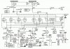
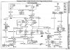
At the module, you have a harness with 6 wires. Unplug it and check the following with a digital volt/ohm meter

Terminal A- Pink wire, should be 12 volts with key in run position. Fuse is in underhood fuse/relay center marked IGN E 10 AMP

Terminal B- Light Blue wire, this is the signal wire from the secondary (rear) fuel tank, using an ohm meter, measure the resistance from a good chassis ground to this wire and should get a reading between 0 and 90 ohms, 0 is empty tank and 90 is full.

Terminal C- Dark Blue with White tracer wire, this is the signal wire from the primary (front) tank, test is same as for terminal B

Terminal D- Light Green wire, this wire controls the Fuel Pump Transfer Relay, with the ENGINE RUNNING and the front lift pump working, GROUND this wire, the Fuel Pump Transfer Relay should click and then you should be able to feel the rear pump working. If the relay clicked and pump is not working, connect a test light across the rear fuel pump harness connector and see if you have power. If lighted, then replace pump, if not lighted replace relay providing you have 12v at Terminal A.

Terminal E- Black with White tracer wire, This is the ground wire for the control module. Using a test light jump from Terminal A to Terminal E with key on, the test light should be lit.
Terminal F- Purple wire, this wire is the output signal to your fuel guage.
Gound this wire it should read empty, leave this wire open, the fuel guage will go pass full.

The fuel pump relay, which is right above the module, has a wiring harness with 4 wires. They are:

Pink Wire is 12 volt from the same source as Terminal A.

Light Green wire (thicker gage) is the feed to the rear fuel pump.

Light Green wire (thin gage) is the control wire from the module as explained in Terminal D.

Gray wire is 12V from the primary pump circuit to energize the Fuel Pump Transfer Relay.
 
we seem to keep the setup the happiest by filling the front first. We also fill it only when doing partial fills. I have heard about people having tons of fun with these, so have fun!
 
we seem to keep the setup the happiest by filling the front first. We also fill it only when doing partial fills. I have heard about people having tons of fun with these, so have fun!

I have been chasing an erratic fuel gauge for over a year now, Just assumed it was the rear sending unit as it was all rotted. Well I replaced that yesterday and it did not change the erratic fuel guage what-so-ever.

Weather permitting I will be checking into this balance module and hope the ground there fixes me up, as the only ground left to clean would be the big one my truck parks on :)

The system's balance module monitors the levels in front tank and rear tank.

Also sends the signal output to the in-cab guage.

Also activates the transfer pump relay to power the rear lift pump.
 
Everything is working as it should,


BUT when I ground the wire to show empty on the gauge it points downward towards my oil pressure (actually interferes with the needle)...

I am keeping a log of the resistance (ohms) of each sending unit, and the position the fuel guage reads.

I have a feeling my guage is off kilter, meaning it may be working alright, but it thinks pointing straight down at 40 oil pressure :) is full, and works away from there.

When I cycle key off and on, it does a few 360's before landing whereever it may.

Over the months it went round and round slowly.

If I monitor my balance transfer and the system is automatically xfering the fuel from rear to front. Then all the gauge reads is the front tanks fuel as the module balances the both.

I may end up doing a separate fuel gauge, however I really don't want to, but I 'm completely out of ideas.

I chased grounds, re-grounded, 2 new sending units.. they are reading ok, balance module checks out ok,...

I followed a couple grounds ... havn't followed the purple lead yet (the one that goes to PCM/fuel gauge)..... PITA.

I feel like I've exhausted my source for help for the first time in a long while.............
 
I'm not sure what the purple output wire of the balance module is supposed to output.

Is it a direct signal that goes to the gauge? Is it a resistance signal? Ohms?
 
The Test: To properly diagnose this, you will need a Vantage/MODIS to check voltage and wave forms. You will also need a wiring diagram for your particular vehicle and will need to determine what the actual problem is with the vehicle. Is the gauge inoperative or inaccurate or does the vehicle run out of fuel even though there is still fuel in at least one tank?

If the gauge is wrong, you will need to take some measurements at the balance module. The signals from the sending units to the module and from the module to the fuel gauge are square waves on this system. Terminal-B (Light Blue) on the module comes from the rear tank sender, terminal-C (Blue/White) is the front tank sender and terminal-F (Purple) is the output to the fuel gauge or PCM/VCM. Set the Vantage/MODIS to Waveform Viewer and check the signals on these three terminals. The square-wave pattern will be taller, toward 12-volts, with more fuel in the tank and shorter, toward 0-volts, with less fuel. If you have an open circuit due to a bad sending unit or a bad ground, you will have a flat 12-volts but no wave pattern.

You can check the senders themselves at the balance-module connector. Unplug the module connector and, referring to your wiring diagram, check resistance between terminals E & B for the rear tank and terminals E & C for the front tank. In both cases, a full tank should result in about 90 ohms and an empty tank should read close to 0 ohms.

What is a vantage / modis? How do I read wave forms so I can figure out if the output from the balance module is correct or not, that way I can figure out what side of the module my problem is at.
 
Fuel Gauge

Magnetic fields of two coils moves the pointer of the fuel gauge. The coils are at right angles to each other. Battery voltage is applied to the E-coil (empty) and the circuit divides at the opposite end of the coil. One path continues to ground through the F-coil (full). Another path goes through CKT 30 (PPL) to ground on single tanks using the variable resistance of the level sensor in the fuel pump and sender (Gasoline) or the fuel gauge sender (Diesel). On dual tank vehicles, CKT 30 (PPL) passes resistance from either the Vehicle Control Module (VCM) (Gas) or the Fuel Pump Balance Module (Diesel).

On gasoline vehicles with dual tanks, the VCM sends a 5 volt reference through CKT 474 (GRY) to the Fuel Pump Balance Module. The Fuel Pump Balance Module sends out a fuel level signal to the senders through either CKT 970 (DK BLU/WHT) for the Primary Sender and CKT 975 (LT BLU) for the Secondary Sender. Ground for both senders runs through CKT 900 (BLK) to the VCM. The Fuel Pump Balance Module will send the return voltage to the VCM through CKT 1589 (PPL/WHT) and the VCM will send the signal onto the Fuel Gauge through CKT 30 (PPL). The fuel pump balance module averages the resistance for vehicles with two fuel tanks. When the tank is low, the resistance of the level sensor is low. A large current flow passes through the E-coil and the pointer moves toward E on the fuel gauge. When the tank is full, the level sensor resistance is high, and less current passes through the E-coil, and the pointer moves toward F on the scale. With two coils operating the pointer, the fuel gauge is not affected by changes in the system's battery voltage.

On diesel vehicles with dual tanks, CKT 30 (PPL) runs directly to the Fuel Pump Balance Module. Grounds for the two fuel tank senders run directly to G104. The remainder of the operation is the same as gasoline.

For single fuel tank vehicles, the fuel gauge includes the following functions:

The level sensor in the fuel gauge sender produces a resistance of about 40 ohms (Gas)/0 ohms (Diesel) empty and about 250 ohms (Gas)/90 ohms (Diesel) full.
A short to ground in the sender or the wiring provides a fully empty indication.
An open in the circuit provides completely full indication.
For dual fuel tank vehicles, the fuel pump balance module does the following functions:

Measures the resistance for both of the fuel senders. Resistance is the same as single tank units.
Averages the resistance and produces an equivalent resistance that reflects the average level of both fuel tanks.
Power to the module, and a change in the input resistance, produces a change in the output resistance to the fuel gauge.
The fuel pump balance module responds to a very low resistance (short to ground) in one or both fuel sender circuits by considering the affected tank(s) to be empty.
A very high resistance (open circuit) in either fuel sender circuit causes the fuel pump balance module to produce a zero output (both tanks empty) signal to the fuel gauge.
Equalizes the level in both of the fuel tanks. Fuel is fed to the engine from the front (primary) fuel tank.
Energizes the fuel pump balance relay when the level in the front tank decreases to about two gallons less than the level in the rear (secondary) fuel tank. This starts the secondary fuel pump which transfers fuel from the rear tank to the front tank.
When the level in the front tank increases to about two gallons greater than the rear tank, the secondary fuel pump stops. This then empties the rear tank first.
 
From what I got now, the purple output wire of the balance module is a balance of the 2 tanks that goes directly to the fuel gauge, so it must be able to be measured in ohms just like the the senders?

The fuel gauge is actually very similar to the senders it seems.

I popped the balance module out of its case and its a PC_Board ... looked in perfect shape.... I'll try measuring the ohms of that purple output wire.

Anyone know what type of signal fuel gauges get? Is it resistance?

Can see how a ground is critical for afuel gauge to operate.

I'm gonna have to take the dash apart and find a ground for that bad boy.
 
Matt I'm in my 98 GM manual now, I don't see any mention as of yet that you have looked at the balance relay, dirty contacts in it could cause flaky operation
 

Attachments

  • 98 6.5 Diesel fuel sender & balance schematic.jpg
    98 6.5 Diesel fuel sender & balance schematic.jpg
    58.6 KB · Views: 130
Last edited:
I know the purple wire feeds the gauge out of the balance MODULE, the relay just runs the rear lp turned on by the module. It is working. I will pull the connections and clean them however, I was under the impression that the relay was after the module, which takes the inputs of the 2 senders, and outputs the fuel gauge feed. It will activate the relay if certain imbalance of 2 tanks. I will try it.

I'll be installing my Monomax's then I'll get to it!
 
I think he means the contacts inside the relay not the connections

I understand what he meant, I just didn't read the ground or the fuel gauge wiring going through those connections.

I havn't had a chance to clean em out, but i did pop it off and there is some coorosion, When I plugged it in my fuel gauge was in a different spot than it was when I unplugged it.

Its raining so no on the back work right now. I'll clean the piss out of it tomorrow with fingers, toes, eyes, toungue, and legs crossed........... :)
 
well, you are blessed with 4wd automatic, the most common setup, so hopefully you can find a cluster. I think that after you have checked everything, all that is left is the cluster. I personally would troll ebay, pick one up for 50 dollars, and give it a try.

Good luck!
 
well, you are blessed with 4wd automatic, the most common setup, so hopefully you can find a cluster. I think that after you have checked everything, all that is left is the cluster. I personally would troll ebay, pick one up for 50 dollars, and give it a try.

Good luck!


What is odd, is that when circuit is wide open, should read full, mine reads closer to empty, when grounded should read empty, I think my gauge is out of calibration, or is loose, meaning it has no home base and is 'freewheeling' or something...

Think with cluster out I could 're-set' the gauge to read full when open contact? or is it sealed unit? Never had one out in recent times to look at.
 
All my grounds are spotless, I even cut G104, and recrimped it incase the factory crimp was bad on the spotless shiny terminal.

Same thing.

I'm just going to get that glowshift fuel gauge. Its more pricey, but with the free shipping, and included pod, its very close price to the cheapies, and FAR more attractive and detailed, with a low fuel light to boot.

Says a microprossor stepper smooths the signal out too, so maybe it wont be all herky jerky and only displays the average over 10 seconds or whatever to be a smooth readout.

I'll order it up tonight and be done with this forever.
 
There. Glowshift seem like really nice gauges. They include daisy chain harnesses for the Power/Ground/Ign/Dimmer 4 wires, so if you add another Glowshift, it makes it really easy... They look fantastic too. Seem high quality. Blow all my other guages away.
 

Attachments

  • Glowshift 001.JPG
    Glowshift 001.JPG
    49.6 KB · Views: 32
  • Glowshift 002.JPG
    Glowshift 002.JPG
    38.6 KB · Views: 28
Back
Top