• Welcome to The Truck Stop! We see you haven't REGISTERED yet.

    Your truck knowledge is missing!
    • Registration is FREE , all we need is your birthday and email. (We don't share ANY data with ANYONE)
    • We have tons of knowledge here for your diesel truck!
    • Post your own topics and reply to existing threads to help others out!
    • NO ADS! The site is fully functional and ad free!
    CLICK HERE TO REGISTER!

    Problems registering? Click here to contact us!

    Already registered, but need a PASSWORD RESET? CLICK HERE TO RESET YOUR PASSWORD!

6.5 grounds

Turbine Doc

Just Another Diesel Guy
Messages
6,278
Reaction score
272
Location
Gautier, Ms./Anywhere Southern USA
From an old post I made on the other site, going to make some improvements along the way but for now lets start with this old post:

Grounds, Grounds, Grounds
Common complaint from folks : “All I ever hear from you guys is check my grounds”

So in an effort to define what we mean here are some of the common ones I'll be posting more as I get my trusty camera out to add to the mix.

Are you having white smoke on startup, slow cranking, errant voltage to lift pump, dim headlights, IP sometimes acts like the fuel solenoid isn’t getting juice, relays aren’t picking up their end of the work.

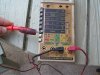
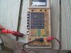
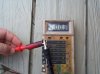
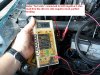
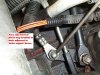
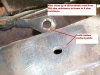
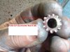
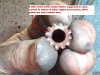
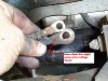
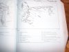
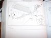
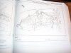
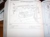
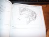
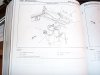
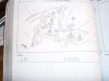
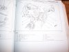
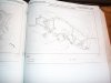
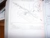
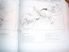
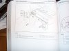
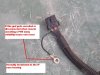
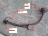
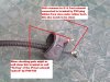
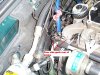
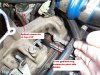
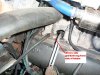
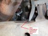
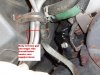
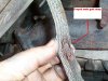
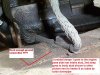
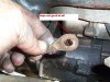
Well here it goes again check your grounds, see attached photos from some preventative maintenance I was doing while swapping passengers side glows, since I had the inner fender off; and one of the main grounds was fully accessible, as an experiment I thought I’d check what my resistance from block to frame was, 300 ohm WOW, with only 14” of GND strap to the frame that is way too high. I had been having intermittent glow issues, but also knew I had at least 1 maybe more bad glow plug on passenger side.

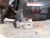
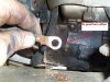
Modern computer controlled engines literally live or die for want of good electron flow, every circuit relies on good solid & clean grounds. Sensors with resistive feedback are impacted by poor grounds, charging & starting circuits, lighting, glow plugs etc. need good grounding. Cleaner the better, poor grounding causes premature device fails as the circuit heats up as it tries to see paths of least resistance. In attached photos cleaning up main grounds resistance frame to block was reduced from 300 ohm to 0 ohm. I don’t have glow problems any more & found only 1 bad glow out of the 8 so maybe 2 things going on in the glow circuit.

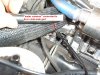
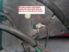
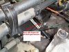
Also take notice of fraying of the strap left unattended/un-inspected, that strap sometimes breaks in half and because it is hidden under the turbo/starter sometimes hard to notice until doing maintenance in that area.

So step one in any problem if you haven’t checked them in a while is take a look at the grounds, all of them.
 

Attachments

  • DCP02017 gnds.JPG
    DCP02017 gnds.JPG
    79.5 KB · Views: 1,668
  • DCP02018 gnds.JPG
    DCP02018 gnds.JPG
    75.2 KB · Views: 1,519
  • DCP02019 gnds.JPG
    DCP02019 gnds.JPG
    66.4 KB · Views: 1,459
  • DCP02117 gnds.JPG
    DCP02117 gnds.JPG
    52.8 KB · Views: 1,444
  • DCP02118 gnds.JPG
    DCP02118 gnds.JPG
    55.6 KB · Views: 1,432
  • DCP02128 gnds.JPG
    DCP02128 gnds.JPG
    63.8 KB · Views: 1,358
  • DCP02129 gnds .jpg
    DCP02129 gnds .jpg
    73.7 KB · Views: 1,379
  • DCP02130 gnds.JPG
    DCP02130 gnds.JPG
    74.4 KB · Views: 1,320
  • DCP02132 gnds.JPG
    DCP02132 gnds.JPG
    70.2 KB · Views: 1,310
  • DCP02131 gnds.JPG
    DCP02131 gnds.JPG
    65.8 KB · Views: 1,327
Now just how does one test for grounds, best way is to use a DMM, Digital multi meter or analog if that is what you have on lowest scale setting you have in resistance check mode indicated on meter with meter powerd on and test leads crossed will show the lowed resistance your meter is capable of going, as close to 0 as you can get is what you are looking for, now 1st place to check is battery cable negative to block both batts, if resistance is high you have bad connection at battery, or bad main gnd lead, or bad connection where batterys connect to the block.

Once you have these cleaned and as close to 0 as you possibly can get then you can connect to any clean surface on the block and a disconnected circuit and you should see same potential to gnd anywhere on the truck, if not and you have high resistance then those circuits are in need of cleaning.

2 pics Meter connected to batt then reading cable through to the block, 0 ohm indicating my cable there is clean, then next would be to do the same on the other battery, then 1 battery neg to the other one you should get the same 0 ohm reading thru the block, then the leads that go block to frame still looking for as close to 0 ohm as possible, if resistance remains high even after cleaning then the wire itself needs to be replaced as it is breaking down.

What circuits are we talking about (17) ground loops for the 6.5 depending which flavor you drive. see Xcel sheet
 

Attachments

  • DCP03846 gnds.jpg
    DCP03846 gnds.jpg
    46.8 KB · Views: 463
  • DCP03847 gnds.jpg
    DCP03847 gnds.jpg
    46.4 KB · Views: 367
  • DCP03848 gnds.jpg
    DCP03848 gnds.jpg
    44.8 KB · Views: 376
  • DCP03850 gnds.JPG
    DCP03850 gnds.JPG
    68.9 KB · Views: 601
  • DCP03849 gnds.JPG
    DCP03849 gnds.JPG
    73.7 KB · Views: 492
XCEL sheet for 17 gnd circuits, where located & what they feed Jim or someone that has it please convert them to open office for me.

JiFaire edit: File converted to pdf and attached in post #12, Tim.
 

Attachments

  • Ground circuits & locations.xls
    32 KB · Views: 871
Last edited by a moderator:
More gnd pics
 

Attachments

  • DCP02708 gnds.JPG
    DCP02708 gnds.JPG
    68.9 KB · Views: 797
  • DCP02165 gnds.JPG
    DCP02165 gnds.JPG
    78.5 KB · Views: 781
  • DCP02164 gnds.JPG
    DCP02164 gnds.JPG
    68.6 KB · Views: 746
  • DCP02136 gnds.JPG
    DCP02136 gnds.JPG
    58.3 KB · Views: 677
  • DCP02135 gnds.JPG
    DCP02135 gnds.JPG
    48.1 KB · Views: 622
  • DCP02134 gnds.JPG
    DCP02134 gnds.JPG
    54.1 KB · Views: 641
  • DCP02133 gnds.JPG
    DCP02133 gnds.JPG
    63.9 KB · Views: 689
These from the manual shot thru the camera, not the best but I will try to scan them later (I hope you guys will appreciate me cuttin/removing pages from my manuals binding to scan them) but for now these will work in a pinch
 

Attachments

  • Gnd G400.JPG
    Gnd G400.JPG
    47.1 KB · Views: 410
  • Gnd G300.JPG
    Gnd G300.JPG
    42.3 KB · Views: 366
  • Gnd G202.JPG
    Gnd G202.JPG
    43.8 KB · Views: 359
  • Gnd G200.JPG
    Gnd G200.JPG
    49.8 KB · Views: 387
  • Gnd G113 .JPG
    Gnd G113 .JPG
    43.8 KB · Views: 395
  • Gnd G108.JPG
    Gnd G108.JPG
    42.4 KB · Views: 420
  • Gnd G104-105.JPG
    Gnd G104-105.JPG
    41.5 KB · Views: 445
  • Gnd 200-201.JPG
    Gnd 200-201.JPG
    44 KB · Views: 558
A few more, I'll dig thru some of my other saved pics to see if I can find pics of actual locations
 

Attachments

  • Gnds G101-102-103.JPG
    Gnds G101-102-103.JPG
    41.3 KB · Views: 220
  • Gnd G404.JPG
    Gnd G404.JPG
    45.1 KB · Views: 232
  • Gnd G401a.JPG
    Gnd G401a.JPG
    42.5 KB · Views: 243
  • Gnd G401.JPG
    Gnd G401.JPG
    44.1 KB · Views: 242
Heres a few that show why it's a dumb idea to remove the gnd from the IP as one remote PMD kit would have you do
 

Attachments

  • PMD-Fuel sol gnd 203.jpg
    PMD-Fuel sol gnd 203.jpg
    48.4 KB · Views: 580
  • PMD-Fuel sol harness gnd 201.jpg
    PMD-Fuel sol harness gnd 201.jpg
    43.4 KB · Views: 555
  • PMD-Fuel sol harness gnd 202.jpg
    PMD-Fuel sol harness gnd 202.jpg
    65.4 KB · Views: 531
Great Thread Tim,
In addition to help maintain these connections use a conductive grease specifically made for preventing corrosion on electrical contacts. A good one being Kopr-Shield by Thomas and Betts, which is what I use commercially in the marine field with excellent results.
http://www.tnb.com/contractor/docs/shamrock.pdf page l11.
A good quality copper based never-sieze is better than nothing in pinch.
Also note not to use the often misinterpreted 'dielectric' grease which is a non-conductive protectant.

Cheers
Nobby
I found that out the hard way:eek:
 
Attachment is pdf of Tim's 'ground locations' file
 

Attachments

  • Ground circuits & locations[1].pdf
    140.5 KB · Views: 696
I found that out the hard way:eek:

This is good to know, as I have used this to protect alot of my grounds too....

However, non conductive grease or not, the contacting surface area of a clean connection should remain intact with any type of sealant, the sealant on the outside protecting coorosion.

I agree, more conducting surface area would defanately apply with a conducting 'sealant'....

Di-electric is still good for close quarters areas such as wire harnesses where cross-conductive-contamination would no doubt happen with a conductive sealant.

I will be getting some other means of conductive sealant.
 
About G200 ground.

"Behind Left side of instrument panel, below fuse block on tie bar"

Does one have to remove the instrument panel to access this? or is the tie bar the round bar that is easy to see if you just look up under the steering column?

Any pictures of a factory tie in?
 
This is good to know, as I have used this to protect alot of my grounds too....

However, non conductive grease or not, the contacting surface area of a clean connection should remain intact with any type of sealant, the sealant on the outside protecting coorosion.

I agree, more conducting surface area would defanately apply with a conducting 'sealant'....

Di-electric is still good for close quarters areas such as wire harnesses where cross-conductive-contamination would no doubt happen with a conductive sealant.

I will be getting some other means of conductive sealant.

The recommended conductive grease is not really a sealant so to speak you apply it between the contacts i.e. the mating surfaces of the lugs and the chassis/engine etc. Also on the threads acts like a never sieze then also. So when using this there is no real need to liberaly paint around the joint as the joint itself has been protected by the grease. I use the Kopr-Kote extensively on marine electrical installs on all the cable lugs etc, come back a couple of years later and the surfaces are as clean as the day I did it.

Agreed one has to be carefull using this from a cross contamination point of view which is where dielectric comes in around small close multiple connections.

Cheers
Nobby
 
The place far too often overlooked is the ground cable ends at the engine block up front.

These suckers will fail in the crimp and you loose the one battery. This starts a cascade effect of voltage trying to find its way home.

One battery feed is good the other is not.

With the engine running, check the voltage at each battery. One battery at 14V and the other at 12V or 13 V or ?????

Likely a ground or the positive connection.

The 94 trucks connect the Alternator to the LH battery and the starter and the main chassis feed come off the RH battery.

95 trucks feed the starter off the RH battery, charge the LH battery and feed the chassis off the LH battery.

If grounds or ?? is bad then something's gonna get Hinky.

I have see rigs that start terrible but the volt meter shows fine when running.

The RH battery had either a poor ground or the crossover +++ was bad or the connection was.

The cables in many cases go sour in the crimps and this can't be seen..

I have seen the RH rear grounds at the intake stud broken off or at least one wire broke.
The braided cable not on the stud or broken.

Grounds are many times overlooked by mechanics when they have stuff off or engine out.

The older rigs were somewhat more forgiving but the electronic injected ones will drive you nuts if the grounds are crap.

These things need 14V showing at the batteries when the engine is running and 14V at the chassis feed stud in the junction box.

Low 13's is not a good sign.

Don't trust the dash gauge either. They often say 13V running but things are fine when checked out front.


CHECK THE GROUNDS

Missy
 
The factory cables have one big issue.
The original ones were surface soldered into the side connectors.
The battery acids over time leak into the cables and they corrode the core of the cable to the point that all that is doing much is the outer few strands of wire that touch the connector at the point of the solder.

Later ones were not soldered either but the result was the same.

If the cables are 5 years old or more I would just replace them.

Sadly the side terminal cables corrode under the molded on jacket and you cant see anything that matters.

Cleaning the part that connects to the battery is always good but wont help a cable that has internal issues.

You can test the cable with an ohm meter and it may read fine, but if the core is corroded the cables ability to handle a heavy amperage load is ZIP, SQUAT, NADA

The Voltage is there but not the amperage flow.
 
Back
Top